Thermally stable ultra-hard material compact construction

Inactive Publication Date: 2006-11-30
SMITH INT INC
42 Cites 214 Cited by

AI-Extracted Technical Summary

Problems solved by technology

A problem known to exist with such conventional PCD materials is that they are vulnerable to thermal degradation during use that is caused by differential thermal expansion characteristics between the interstitial solvent catalyst material and the intercrystalline bonded diamond.
Such differential thermal expansion is known to occur at temperatures of about 400° C., which can cause ruptures to occur in the diamond-to-diamond bonding that can result in the formation of cracks and chips in the PCD structure.
Specifically, the solvent metal catalyst is known to cause an undesired catalyzed phase transformation in diamond (converting it to carbon monoxide, carbon dioxide, or graphite) with increasing temperature, thereby limiting practical use of the PCD material to about 750° C.
A problem, however, with this approach is that the lack of solvent metal catalyst within the PCD body precludes the subsequent attachment of a metallic su...

Benefits of technology

[0015] The ultra-hard material body, intermediate material, and substrate are joined together by high pressure/high temperature process. During this high pressure/high temperature process, any ultra-hard material elements, bodies, or layers that are combined are joined together to form a desired composite ultra-hard material body, and the body is joined to the substrate. Ultra-hard material compact constructions of this invention provide improved properties of thermal stabil...

Abstract

Thermally stable ultra-hard compact constructions of this invention comprise an ultra-hard material body that includes a thermally stable region positioned adjacent a surface of the body. The thermally stable region is formed from consolidated materials that are thermally stable at temperatures greater than about 750° C. The thermally stable region can occupy a partial portion of or the entire ultra-hard material body. The ultra-hard material body can comprise a composite of separate ultra-hard material elements that each form different regions of the body, at least one of the regions being thermally stable. The ultra-hard material body is attached to a desired substrate, an intermediate material is interposed between the body and the substrate, and the intermediate material joins the substrate and body together by high pressure/high temperature process.

Application Domain

Technology Topic

Image

  • Thermally stable ultra-hard material compact construction
  • Thermally stable ultra-hard material compact construction
  • Thermally stable ultra-hard material compact construction

Examples

  • Experimental program(1)

Example

EXAMPLE
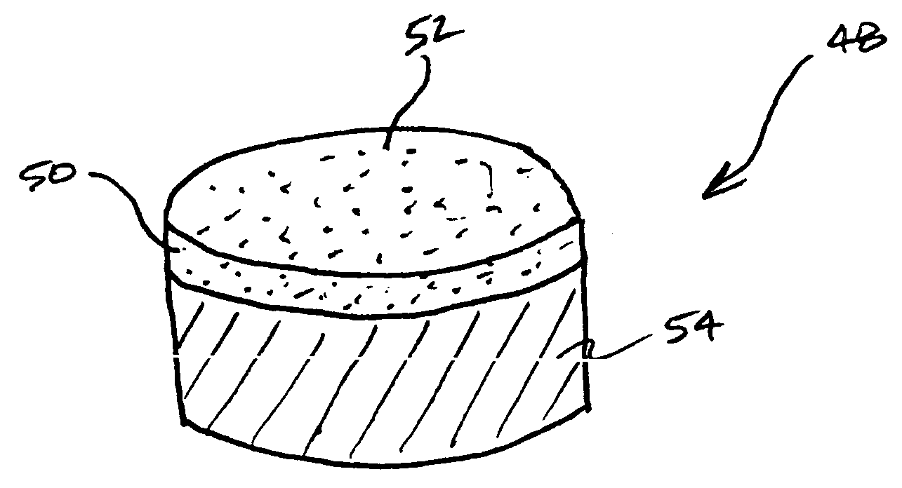
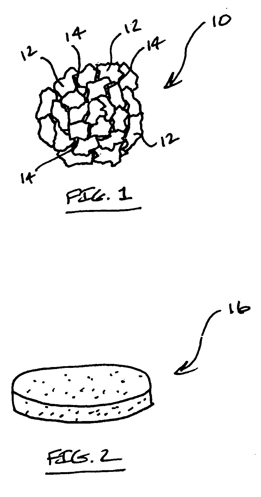
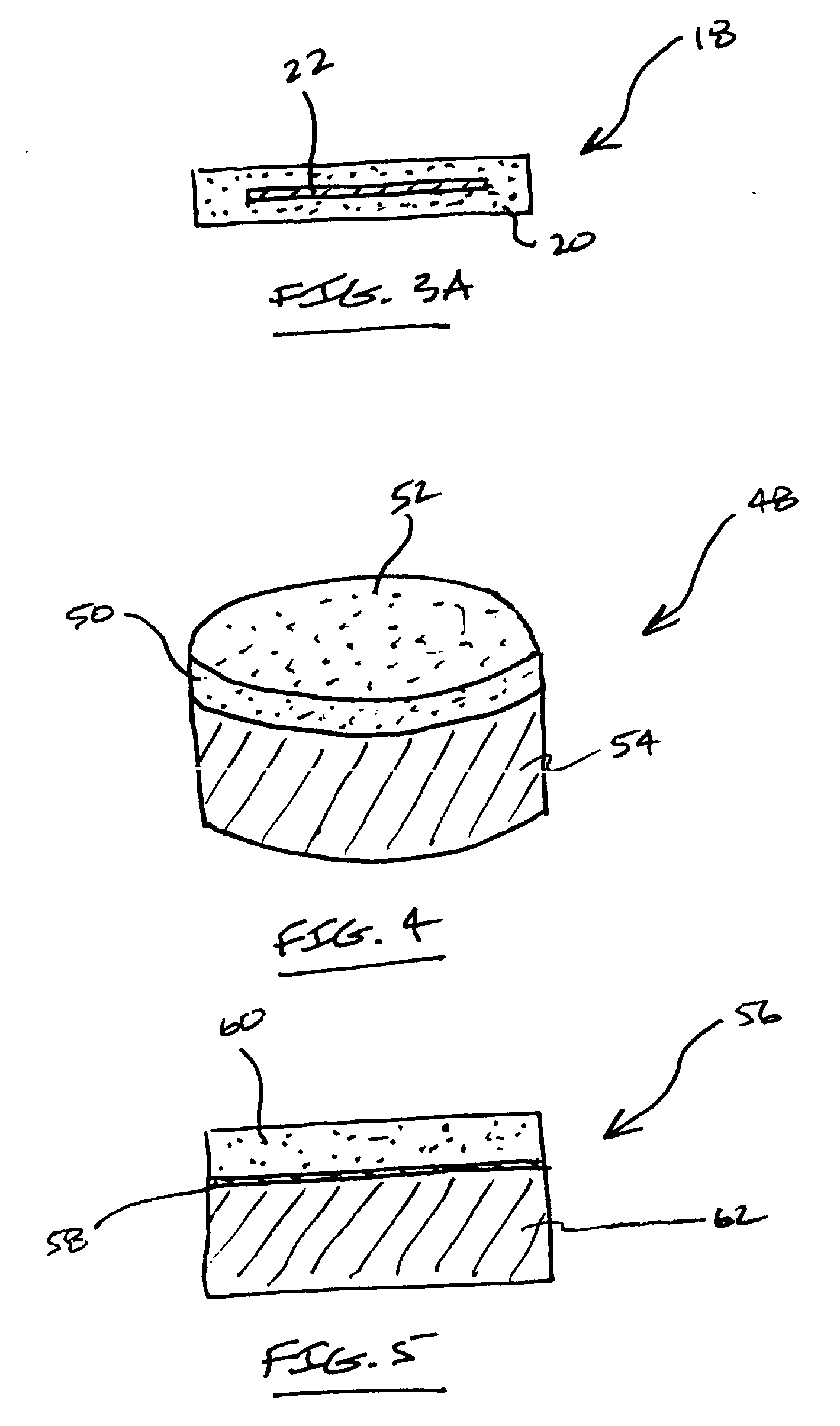
Thermally Stable Ultra-Hard Material Compact
[0082] Synthetic diamond powders having an average grain size of approximately 2-50 micrometers are mixed together for a period of approximately 2-6 hours by ball milling. The resulting mixture includes approximately six percent by volume cobalt solvent metal catalyst based on the total volume of the mixture, and is cleaned by heating to a temperature in excess of 850° C. under vacuum. The mixture is loaded into a refractory metal container and the container is surrounded by pressed salt (NaCl), and this arrangement is placed within a graphite heating element. This graphite heating element containing the pressed salt and the diamond powder encapsulated in the refractory container is then loaded in a vessel made of a high-pressure/high-temperature self-sealing powdered ceramic material formed by cold pressing into a suitable shape. The self-sealing powdered ceramic vessel is placed in a hydraulic press having one or more rams that press anvils into a central cavity. The press is operated to impose a pressure and temperature condition of approximately 5,500 MPa and approximately 1,450° C. on the vessel for a period of approximately 20 minutes.
[0083] During this HPHT processing, the cobalt solvent metal catalyst infiltrates through the diamond powder and catalyzes diamond-to-diamond bonding to form PCD having a material microstructure as discussed above and illustrated in FIG. 1. The container is removed from the device, and the resulting PCD diamond body is removed from the container and subjected to acid leaching. The PCD diamond body has a thickness of approximately 1,500 micrometers. The entire PCD body is immersed in an acid leaching agent comprising hydrofluoric acid and nitric acid for a period time sufficient to render the diamond body substantially free of the solvent metal catalyst.
[0084] The so-formed thermally stable diamond body is then prepared for loading into a refractory metal container for further HPHT processing by placing a refractory metal foil layer adjacent an interface surface of the diamond body, and placing a substrate adjacent the refractory metal foil layer. The refractory metal is Molybdenum, and the foil layer has a thickness of approximately 100 micrometers. The substrate is formed from WC—Co and has a thickness of approximately 12 millimeters. The combined thermally stable diamond body, refractory metal foil layer, and substrate are loaded into the container, the container is surrounded by pressed salt (NaCl) and this arrangement is placed within a graphite heating element as noted above for the first HPHT process. This assembly is then loaded in the vessel made of a high-pressure/high-temperature self-sealing powdered ceramic material formed by cold pressing into a suitable shape. The self-sealing powdered ceramic vessel is placed in the hydraulic press, and the press is operated to impose a pressure and temperature condition of approximately 5.5 GPa and approximately 1,200° C. on the vessel for a period of approximately 5 minutes.
[0085] During this second HPHT processing, the refractory metal foil layer reacts with the diamond body and substrate, and thereafter reacts with the diamond in the diamond body forming carbide. In addition to any bond provided with the diamond body by virtue of this reaction, plastic deformation of the refractory metal at the interface between the diamond and substrate operate to form an interlocking mechanical bond therebetween. The refractory meal foil layer also operates as a barrier to prevent unwanted infiltration of cobalt from the substrate into the diamond body. The container is removed from the device, and the resulting thermally stable diamond compact construction, comprising the thermally stable diamond body bonded to the substrate, is removed from the container. Subsequent examination of the compact reveals that the thermally stable diamond body is well bonded to the substrate.
[0086] This compact is machined to the desired size using techniques known in the art, such as by grinding and lapping. It is then tested in a dry high-speed lathe turning operation where the compact is used to cut a granite log without coolant. The thermally stable ultra-hard material compact of this invention displayed an effective service life that was greater than twice that of a conventional PCD compact.
[0087] A feature of thermally stable ultra-hard material compact constructions of this invention is that they include an ultra-hard material body having at least a region that is thermally stable, and that the body is attached to a substrate. A further feature is that the substrate is attached to the ultra-hard material body during a HPHT process separate from that used to form the ultra-hard material body to produce a strong bond therebetween. The bond strength between the ultra-hard material body and the substrate resulting from this process is much higher than that which can be achieved by other methods of attaching a substrate to thermally stable ultra-hard material bodies due to the ability to provide the bond at higher temperatures and pressures, while also preventing any diamond in the body from graphitizing.
[0088] Further, because the substrate is bonded to the ultra-hard material body, e.g., in the form of a thermally-stable diamond body, at a temperature that is generally below that used to form PCD, compacts formed according to this invention may have a more favorable distribution of residual stresses than compacts formed in a single HPHT cycle during which time both the PCD is formed and a substrate is attached thereto. In such a single HPHT cycle, the high temperatures necessary to form PCD are known to produce high levels of residual stress in the compact due to the relative differences in the thermal expansion properties of the PCD body and the substrate and due to shrinkage stresses created during sintering of the PCD material.
[0089] Further, because thermally stable ultra-hard material compact constructions of this invention are specifically engineered to permit the attachment of conventional types of substrates thereto, e.g., formed from WC—Co, attachment with different types of well known cutting and wear devices such as drill bits and the like are easily facilitated by conventional attachment techniques such as by brazing or welding.
[0090] Further still, thermally stable ultra-hard material compact constructions of this invention can include the use of an intermediate layer for the purpose of enhancing the bond strength, and/or preventing infiltration of solvent catalyst materials, and/or minimizing the difference in mechanical properties such as the coefficient of thermal expansion between the substrate and the body. Still further, thermally stable ultra-hard material compact constructions of this invention can include a ultra-hard body having a composite or laminate construction formed from a number of bodies that are specifically selected and joined together during the HPHT process to provide a resulting composite ultra-hard body having specially tailored properties of thermal stability, wear resistance, and fracture toughness.
[0091] Thermally stable ultra-hard material compact constructions of this invention can be used in a number of different applications, such as tools for mining, cutting, machining and construction applications, where the combined properties of thermal stability, wear and abrasion resistance are highly desired. Thermally stable ultra-hard material compact constructions of this invention are particularly well suited for forming working, wear and/or cutting components in machine tools and drill and mining bits such as roller cone rock bits, percussion or hammer bits, diamond bits, and shear cutters.
[0092]FIG. 7 illustrates an embodiment of a thermally stable ultra-hard material compact construction of this invention provided in the form of a cutting element embodied as an insert 76 used in a wear or cutting application in a roller cone drill bit or percussion or hammer drill bit. For example, such inserts 76 can be formed from blanks comprising a substrate portion 78 formed from one or more of the substrate materials 80 disclosed above, and an ultra-hard material body 82 having a working surface 84 formed from the thermally stable region of the ultra-hard material body. The blanks are pressed or machined to the desired shape of a roller cone rock bit insert.
[0093]FIG. 8 illustrates a rotary or roller cone drill bit in the form of a rock bit 86 comprising a number of the wear or cutting inserts 76 disclosed above and illustrated in FIG. 7. The rock bit 86 comprises a body 88 having three legs 90, and a roller cutter cone 92 mounted on a lower end of each leg. The inserts 76 can be fabricated according to the method described above. The inserts 76 are provided in the surfaces of each cutter cone 92 for bearing on a rock formation being drilled.
[0094]FIG. 9 illustrates the inserts 76 described above as used with a percussion or hammer bit 94. The hammer bit comprises a hollow steel body 96 having a threaded pin 98 on an end of the body for assembling the bit onto a drill string (not shown) for drilling oil wells and the like. A plurality of the inserts 76 (illustrated in FIG. 7) are provided in the surface of a head 100 of the body 96 for bearing on the subterranean formation being drilled.
[0095]FIG. 10 illustrates a thermally stable ultra-hard material compact construction of this invention as embodied in the form of a shear cutter 102 used, for example, with a drag bit for drilling subterranean formations. The shear cutter 102 comprises a thermally stable ultra-hard material body 104 that is sintered or otherwise attached/joined to a cutter substrate 106. The thermally stable ultra-hard material body includes a working or cutting surface 108 that is formed from the thermally stable region of the ultra-hard material body.
[0096]FIG. 11 illustrates a drag bit 110 comprising a plurality of the shear cutters 102 described above and illustrated in FIG. 10. The shear cutters are each attached to blades 112 that extend from a head 114 of the drag bit for cutting against the subterranean formation being drilled.
[0097] Other modifications and variations of thermally stable ultra-hard material compact constructions will be apparent to those skilled in the art. It is, therefore, to be understood that within the scope of the appended claims, this invention may be practiced otherwise than as specifically described.

PUM

PropertyMeasurementUnit
Temperature750.0°C
Temperature1000.0°C
Depth1.0E-4m
tensileMPa
Particle sizePa
strength10

Description & Claims & Application Information

We can also present the details of the Description, Claims and Application information to help users get a comprehensive understanding of the technical details of the patent, such as background art, summary of invention, brief description of drawings, description of embodiments, and other original content. On the other hand, users can also determine the specific scope of protection of the technology through the list of claims; as well as understand the changes in the life cycle of the technology with the presentation of the patent timeline. Login to view more.

Similar technology patents

Improved peptide pharmaceuticals

ActiveUS20150307550A1Improve propertyTetrapeptide ingredientsSaccharide peptide ingredientsDrugPeptide
Owner:MEDERIS DIABETES

Use of Bacteria for the Production of Bioenergy

ActiveUS20110104766A1Promote modificationImprove propertyBiofuelsFermentationBiomassDeinococcus
Owner:CENT NAT DE LA RECHERCHE SCI +1

Classification and recommendation of technical efficacy words

  • Facilitate attachment
  • Improve property

Thermally stable ultra-hard polycrystalline materials and compacts

InactiveUS20070187155A1Improved property of thermal stability , wear resistance and hardnessFacilitate attachmentDrill bitsConstructionsBoron nitrideSingle element
Owner:SMITH INT INC

Plastic pallet

Owner:POWELL JOE A

Thermally stable diamond polycrystalline diamond constructions

ActiveUS20060060391A1Enhanced degree of thermal stabilityFacilitate attachmentDrill bitsConstructionsPolycrystalline diamondMetallic substrate
Owner:SMITH INT INC

Liquid crystal display

InactiveUS20050030444A1Improve propertyEnhance front contrastDiffusing elementsNon-linear opticsDiffusionCrystallography
Owner:FUJIFILM CORP
Why Eureka
Try Eureka