Phase shifter for laser annealing
- Summary
- Abstract
- Description
- Claims
- Application Information
AI Technical Summary
Benefits of technology
Problems solved by technology
Method used
Image

Examples
embodiment 1
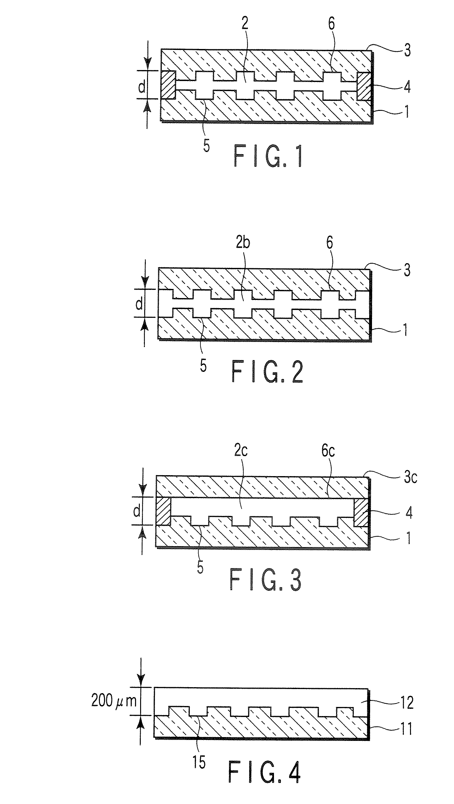
[0046]FIG. 1 shows a schematic sectional structure of a phase shifter for laser annealing in the present invention. In the drawing, reference number 1 denotes a first layer, 2 denotes a second layer, and 3 denotes a third layer.
[0047] The first layer 1 and the third layer 3 are made of, for example, quartz glass. A two-dimensional pattern is formed with a fine grooves 5 (stepped portions) in the surface of the first layer 1. Similarly, a two-dimensional pattern is formed with fine grooves 6 (stepped portions) in the surface of the third layer 3. The first layer 1 and the third layer 3 are arranged so that the second layer 2 is sandwiched between the first layer and the third layer in a state in which the surfaces provided with the grooves 5, 6 face each other. A peripheral edge portion of the first layer 1 is laminated on that of the third layer 3 via a spacer 4.
[0048] In this example, the second layer 2 is constituted of an inactive gas introduced between the first layer 1 and th...
embodiment 2
[0051]FIG. 2 shows another example of a cross-sectional structure of a phase shifter for laser annealing in the present invention. A sectional shape of each layer is the same as that of the above example shown in FIG. 1.
[0052] In this example, a first layer 1 and a third layer 3 are made of quartz glass, and a second layer 2b is made of porous silica (e.g., trade name “Silica Aerogel” manufactured by U.S. Aerogel Inc.). Porous silica has a light refractive index of 1.01 to 1.06, which is remarkably close to that of air. There is a sufficient difference from quartz glass (refractive index: 1.45) constituting the first layer 1 and the third layer 3. Furthermore, porous silica has a comparatively high transmittance of about 80% with respect to the laser light (wavelength: 248 nm) emitted from KrF excimer laser, and decay of the laser light passed through the phase shifter can be minimized.
[0053] This phase shifter will be assembled as follows. Porous silica is sandwiched between the ...
embodiment 3
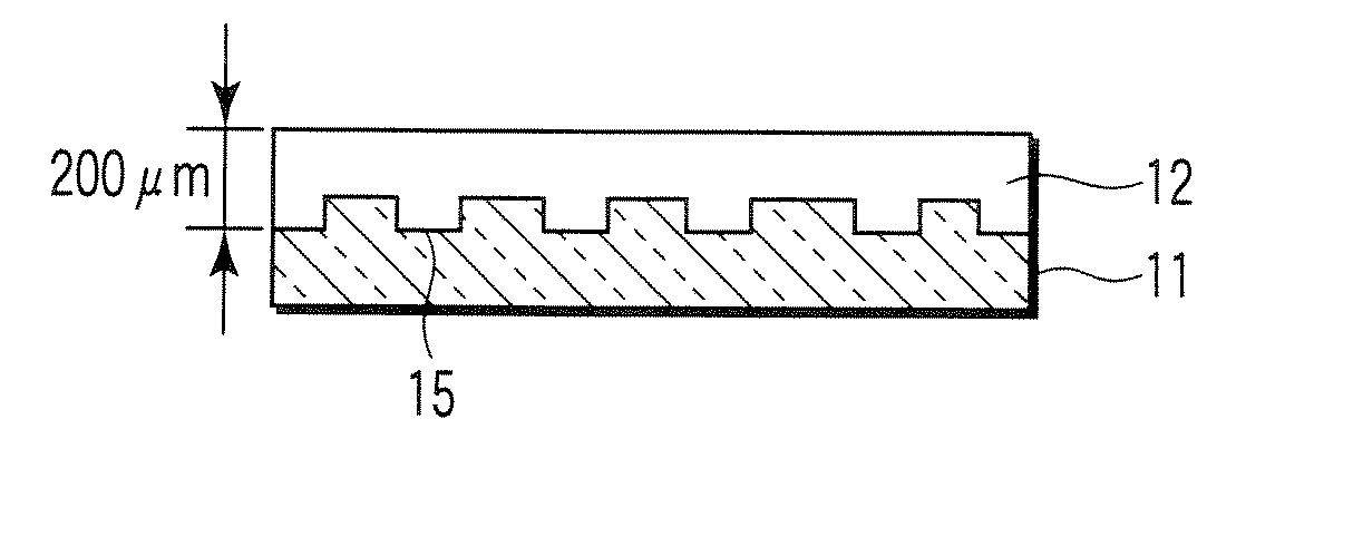
[0054]FIG. 3 shows still another example of a sectional structure of a phase shifter for laser annealing in the present invention. This example is a modification of the above example shown in FIG. 1. In this example, a third layer 3c is constituted of a flat plate of quartz glass. That is, any two-dimensional pattern of fine stepped portions is not formed in an interface 6c between a second layer 2c and the third layer 3c. Another respect is similar to that of the above example shown in FIG. 1.
PUM
| Property | Measurement | Unit |
|---|---|---|
| Transmittivity | aaaaa | aaaaa |
| Thickness | aaaaa | aaaaa |
| Width | aaaaa | aaaaa |
Abstract
Description
Claims
Application Information