Work piece processing by pulsed electric discharges in solid-gas plasma

a pulsed electric discharge and solid-gas plasma technology, applied in the direction of electrodes, diaphragms, ion implantation coatings, etc., can solve the problems of more difficult interface mixing by film deposition using preferably metal vapor than the one used in the field of high-current pulsed electric discharge of work pieces in solid-gas plasmas

Active Publication Date: 2006-12-14
BRANNSTOM RUNE +1
View PDF3 Cites 31 Cited by
  • Summary
  • Abstract
  • Description
  • Claims
  • Application Information

AI Technical Summary

Benefits of technology

[0036] It is an object of the invention to provide an efficient method of processi

Problems solved by technology

It is obvious that this method has a very limited practical value.
However, the use of only plasma confinement does not allow achieving metal plasma parameters that are necessary for an efficient use of the processes as described by Cheng et al. and Gilmore et al, see the discussion below.
It is obvious that interface mixing by film deposition using preferably metal vapor is more problematic than using plasma deposition because plasma ions can be accelerated up to high energy by work piece biasing.
For developing these materials and in particular deposition methods for depositing material deeply into narrow holes by magnetron sputtering much effort has been made.
A main problem arising in this process is the randomised velocity space distribution of neutrals and ions that are used for filling vias or for depositing material in vias.
That results in a non-directional via deposition.
Therefore, the filling of vias having an aspect ratio of more than about 5:1 becomes difficult but modern and fu

Method used


Image

  • Work piece processing by pulsed electric discharges in solid-gas plasma
  • Work piece processing by pulsed electric discharges in solid-gas plasma
  • Work piece processing by pulsed electric discharges in solid-gas plasma

Examples


Embodiment Construction

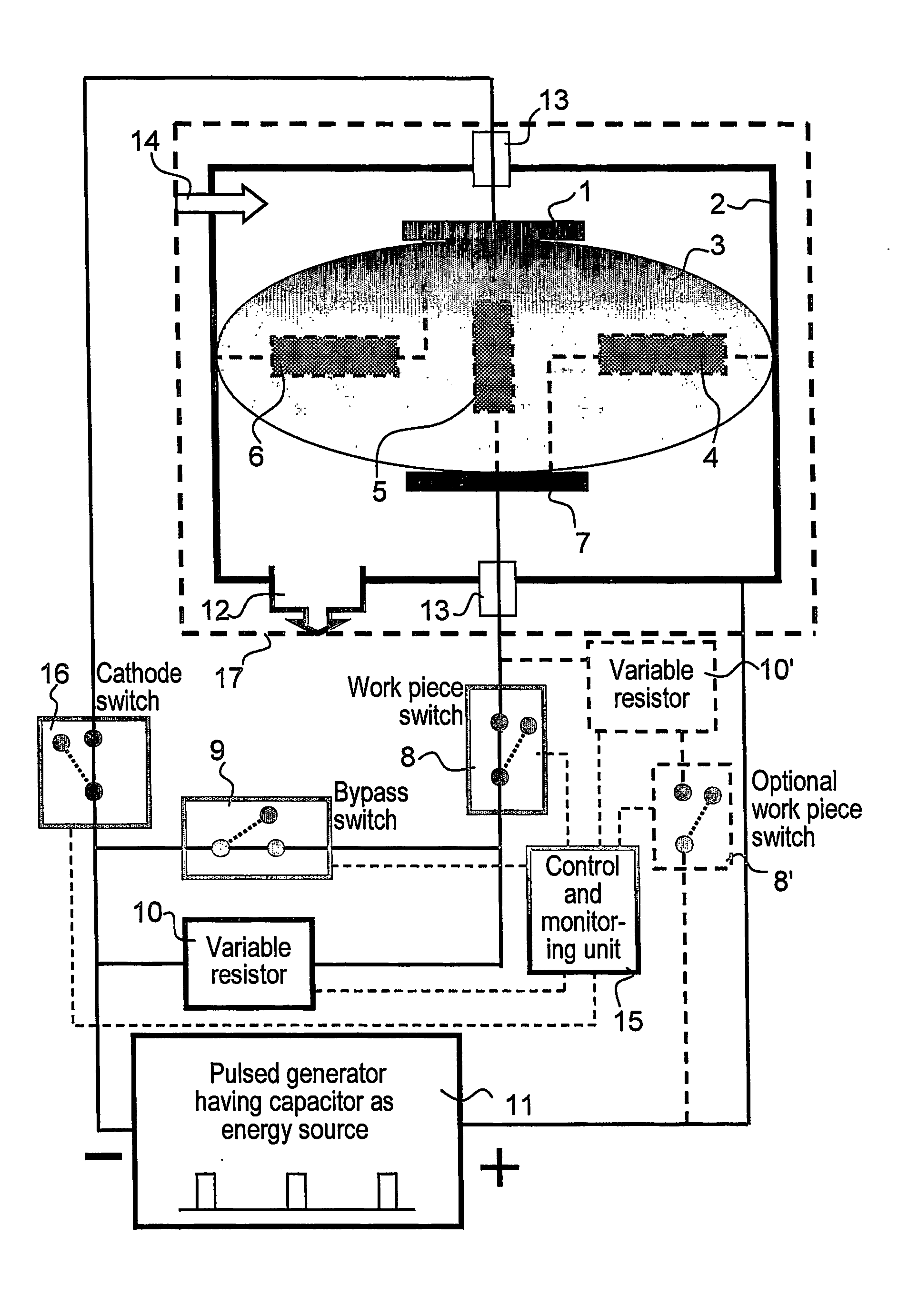
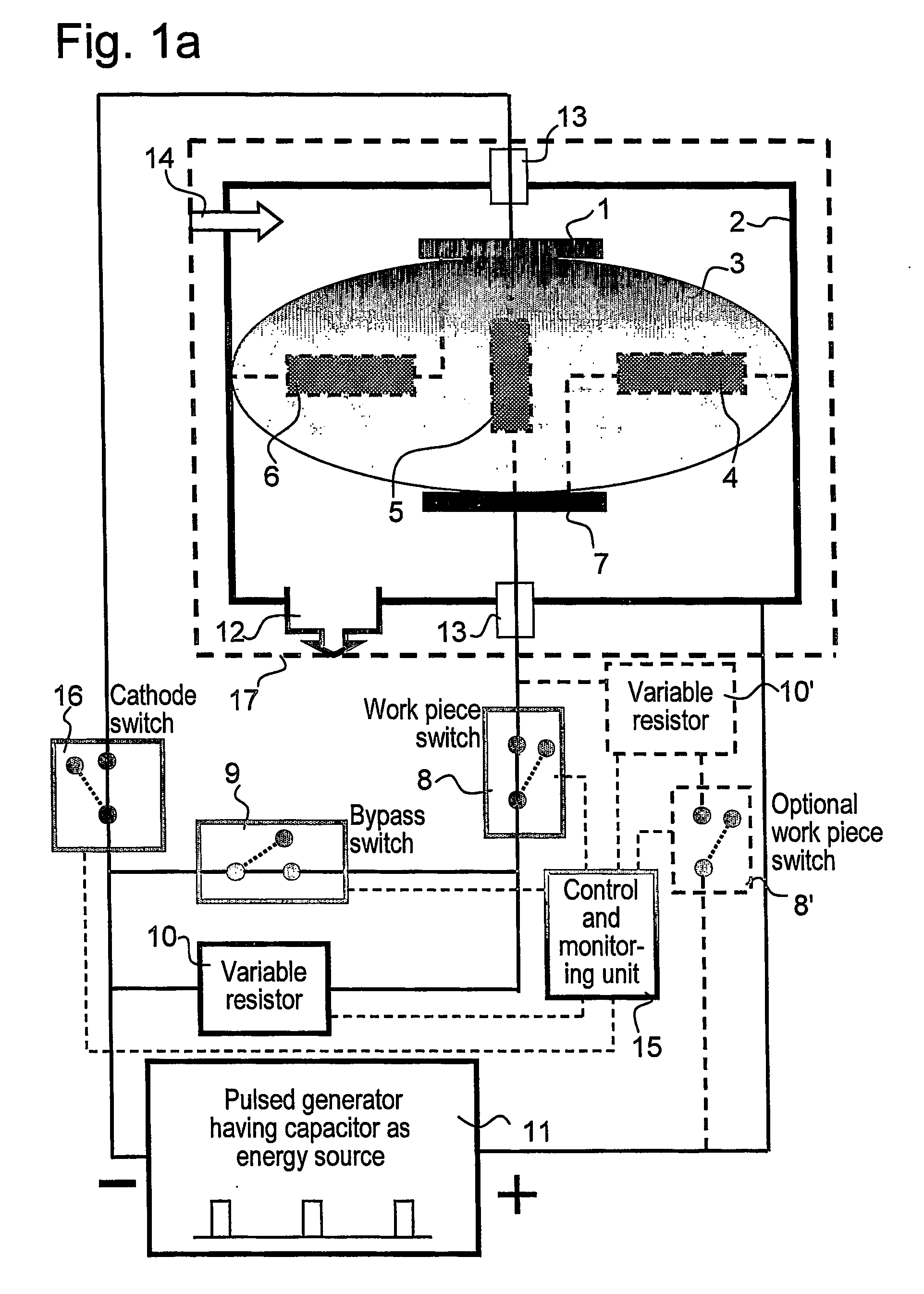
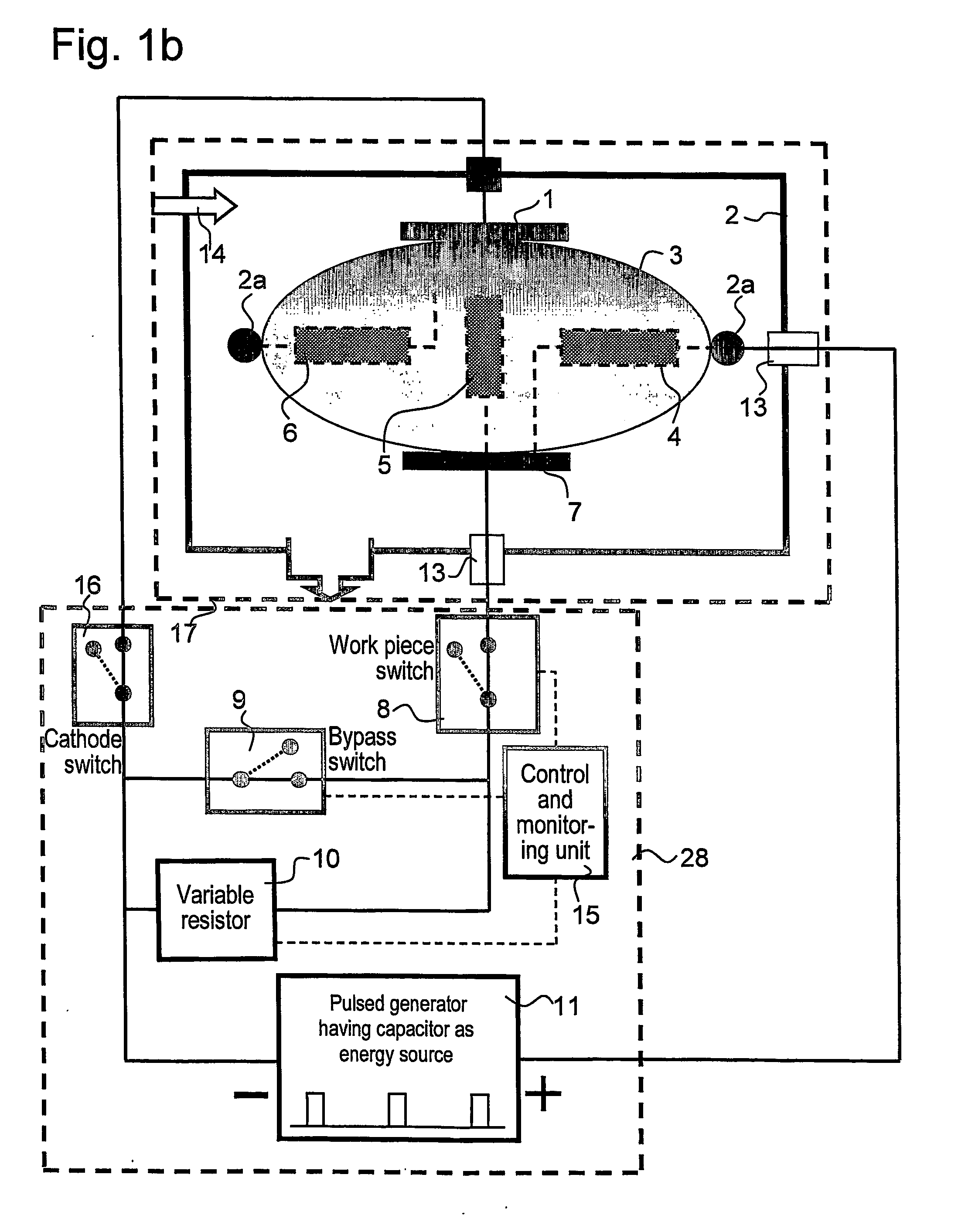
[0074] For processing a work piece, in particular for modifying the surface thereof, a pulsed ion current can be applied to flow between an anode and the work piece through a periodically produced dense plasma supplied by an independent pulsed plasma generator that is operating in a pulsed regime with a magnetron sputtering cathode. The plasma can be composed of ionized gas atoms and ionized metal atoms, i.e. of gas and metal plasmas. The metal atoms are sputtered from some metal surface to form a metal vapor that is partly ionized and the ratio between the metal plasma portion and the metal vapor portion, i.e. the metal vapor ionization degree or rate, as well as the ratio between ionized metal atoms and ionized gas atoms in the plasmas are variable. The anode and the work piece act together as an electric diode such as in a discharge system. The plasma is produced by high current pulsed electric discharges between the anode and the magnetron sputtering cathode. Discharges are prod...


PUM

PropertyMeasurementUnit
Timeaaaaaaaaaa
Timeaaaaaaaaaa
Electric potential / voltageaaaaaaaaaa

Abstract

Work piece processing is performed by pulsed discharges between an anode (2) and a magnetron sputtering cathode (1) in solid-gas plasmas using a chamber (2) containing the work piece (7). A system (12) maintains a vacuum in the chamber and another system (14) provides sputtering and reactive gases. The pulses are produced in a plasma pulser circuit including the anode and the cathode, the discharges creating gas and partially ionized solid plasma blobs (3) moving or spreading from a region at a surface of the cathode towards the work piece and the anode. A potential is applied to the work piece so that a pulsed current comprising biasing pulses arises between the second electrodes. In particular biasing discharges are produced between the anode and the work piece when said plasma blobs have spread to regions at the anode and at the work piece so that the pulsed current is the current of these biasing discharges. The method is efficient for processing or modifying surface regions of work pieces of various kinds and configurations and can be employed for achieving efficient work piece etching, interface mixing, surface and balk diffusion, gas absorption and desorption, initial and further stages of thin film condensation, and for performing ion plating.

Description

RELATED APPLICATIONS [0001] This application claims priority and benefit from Swedish patent application No. 0302045-0, filed Jul. 10, 2003, the entire teachings of which are incorporated herein by reference. FIELD OF THE INVENTION [0002] The present invention relates to processing work pieces by high current pulsed electric discharges in solid-gas plasmas, produced by high current pulsed discharges in a gas located in a magnetron magnetic field configuration. BACKGROUND [0003] Deposition techniques based on surface modification and thin film condensation by gas / metal plasmas play an increasing role in coating processes for different applications, in particular for making mechanical, electronic, protective and optical coatings. A main advantage of plasma assisted technology is derived from the possibility of varying the energy and trajectories of ions arriving from a plasma to a work piece surface during surface preparation for thin film deposition and initial and further stages of ...

Claims


Application Information

Patent Timeline
IPC IPC(8): C23C14/32C23C14/00C23C14/34C23C14/35H01J37/34
CPCC23C14/345H01J37/3405H01J37/32697C23C14/351H01J37/3444C23C14/3485
Inventor KOUZNETSOV, VLADIMIR
Owner BRANNSTOM RUNE
Why Eureka
Try Eureka