Reprogrammable fuse structure and method

a fuse structure and reprogrammable technology, applied in the field of integrated circuits, can solve the problems that the majority if not all phase change fuse cells cannot be directly heated, and achieve the effects of reducing the applied current, minimizing the additional processing steps, and convenient implementation

Inactive Publication Date: 2006-12-14
GLOBALFOUNDRIES INC
View PDF30 Cites 49 Cited by
  • Summary
  • Abstract
  • Description
  • Claims
  • Application Information

AI Technical Summary

Benefits of technology

[0010] This reprogrammable fuse structure provides advantage over the prior-art reprogrammable chalcogenide fuse structure in several aspects. The proposed structure enables lower applied currents and voltages required to change the state of the fuse through utilization of direct heating

Problems solved by technology

Modeling of indirect heating vs. direct heating indicates that indirect heating is not feasible f

Method used


Image

  • Reprogrammable fuse structure and method
  • Reprogrammable fuse structure and method
  • Reprogrammable fuse structure and method

Examples


Embodiment Construction

[0024] A Structure According to the Present Invention

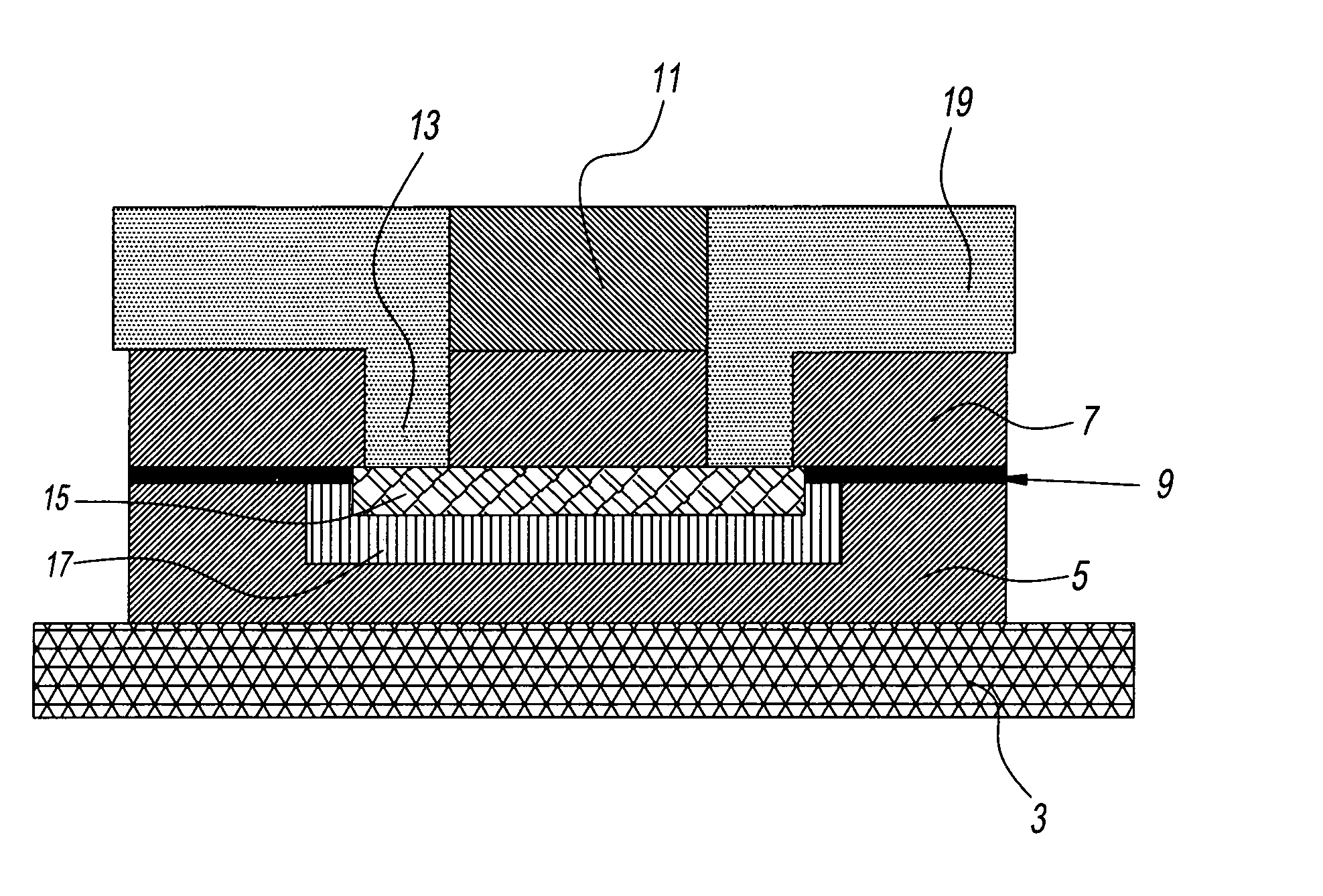
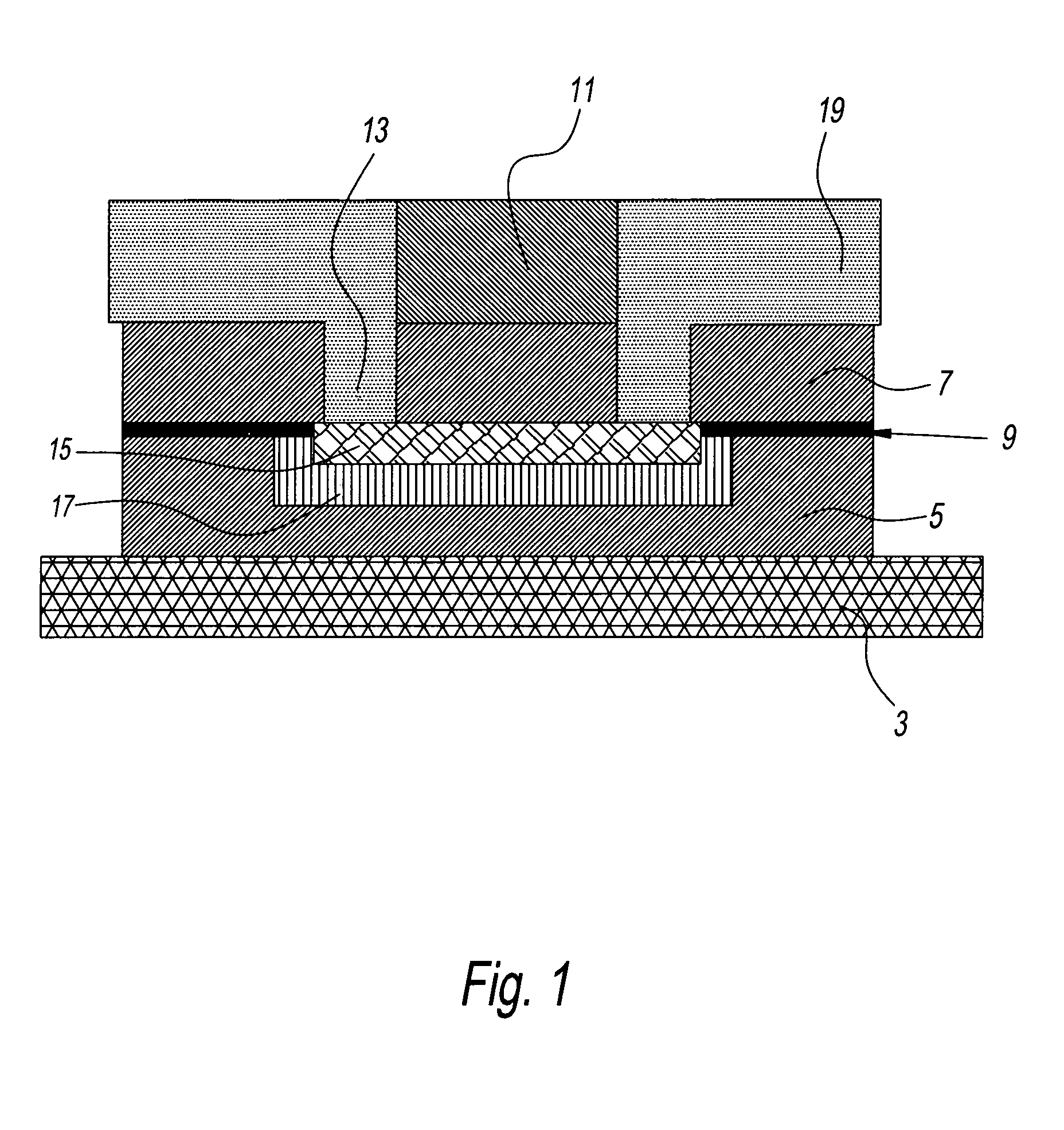
[0025] Referring to FIG. 1, a reprogrammable fuse structure within an electrical interconnect structure, has substrate 3, a line level dielectric layer 5, a short line of phase change material 15 forming the fuse cell within the line level dielectric layer extending partially through the thickness of the line level dielectric layer, a thin capping dielectric layer atop said line level dielectric layer 9, a via level dielectric layer 7 containing two via's 13 which are in contact with the surface of the phase change material in the first line level dielectric layer forming the anode and cathode of the fuse cell, and a second line level dielectric layer 11 atop said via level dielectric layer containing lines 19 in contact with the via's in the via level dielectric layer. This reprogrammable fuse structure has associated control circuitry to change the state of the phase change material from the higher resistivity state to the lowe...


PUM


Abstract

A reversible fuse structure in an integrated circuit is obtained through the implementation of a fuse cell having a short thin line of phase change materials in contact with via and line structures capable of passing current through the line of phase change material (fuse cell). The current is passed through the fuse cell in order to change the material from a less resistive material to a more resistive material through heating the phase change material in the crystalline state to the melting point then quickly quenching the material into the amorphous state. The reversible programming is achieved by passing a lower current through the fuse cell to convert the high resistivity amorphous material to a lower resistivity crystalline material. Appropriate sense-circuitry is integrated to read the information stored in the fuses, wherein said sense circuitry is used to enable or disable circuitry.

Description

BACKGROUND OF THE INVENTION [0001] 1. Field of the Invention [0002] The present invention relates generally to the field of integrated circuits. More particularly, the present invention relates to reversible fusible link programming through utilization of phase change materials in semiconductor integrated circuits. [0003] 2. Description of the Related Art [0004] Redundancy in integrated circuit memories is part of the current chip manufacturing strategy to improve yield. By replacing defective cells with duplicate or redundant circuits on chips, integrated circuit memory yields are significantly increased. The current practice is to blow conductive connections (fuses), thereby allowing the redundant memory cells to be used in place of non functional cells. It is also common practice to provide for customization of chips and modules to adapt chips to specific applications. By selectively blowing fuses within an integrated circuit having multiple potential uses, a single integrated ci...

Claims


Application Information

Patent Timeline
IPC IPC(8): H01L27/10H01L29/73
CPCH01L23/5252H01L23/5256H01L45/06H01L45/1206H01L45/1226H01L45/1286H01L45/1293H01L2924/0002H01L45/144H01L45/148H01L45/1683H01L2924/3011H01L2924/00H10N70/231H10N70/253H10N70/823H10N70/8613H10N70/8616H10N70/8828H10N70/884H10N70/066
Inventor BURR, GEOFFREY W.KOTHANDARAMAN, CHANDRASEKHARANLAM, CHUNG HONLIU, XIAO HUROSSNAGEL, STEPHEN M.TYBERG, CHRISTY S.WISNIEFF, ROBERT L.
Owner GLOBALFOUNDRIES INC
Why Eureka
Try Eureka