Illuminating device, and image display apparatus incorporating same

a technology of illumination device and image display device, which is applied in the direction of lighting and heating apparatus, color television, semiconductor devices, etc., can solve the problems of low reliability of blue and green light semiconductor laser diodes presently, large size and high cost, and large size of illumination optical system b>201/b>, so as to reduce the size and weight, the effect of reducing the dimension and weigh

Inactive Publication Date: 2006-12-14
MINEBEA CO LTD
View PDF5 Cites 12 Cited by
  • Summary
  • Abstract
  • Description
  • Claims
  • Application Information

AI Technical Summary

Benefits of technology

[0022] Since the illuminating device of the image display apparatus can be drastically reduced in dimension and weight, and also can be battery-driven by a simple driving circuit, the image display apparatus achieves reduction in dimension and weight thus readily providing a projection typ

Problems solved by technology

However, for example, in the optical system shown in FIG. 10, if the aforementioned LED array is used in place of the discharge lamp 10, the following problem is caused.
Thus, the illumination optical system 201 is forced to be large in size and high in cost.
Thus, the illumination optical system 301 is forced to see an increase in size and cost.
Also, the aforementioned Japanese Patent Applications Laid-Ope

Method used


Image

  • Illuminating device, and image display apparatus incorporating same
  • Illuminating device, and image display apparatus incorporating same
  • Illuminating device, and image display apparatus incorporating same

Examples


first embodiment

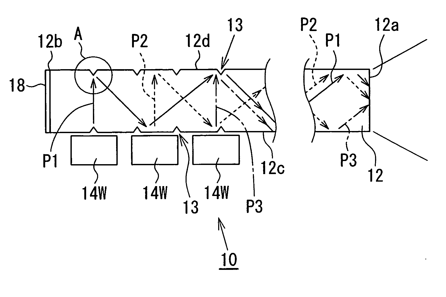
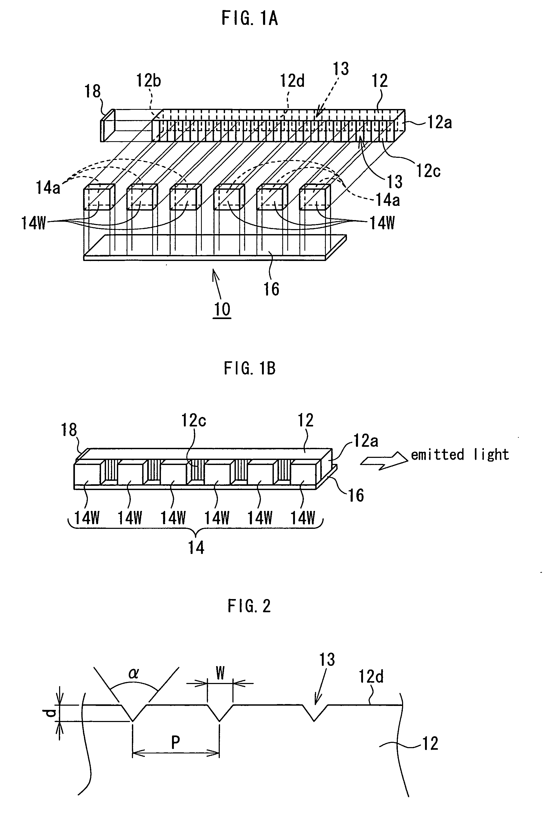
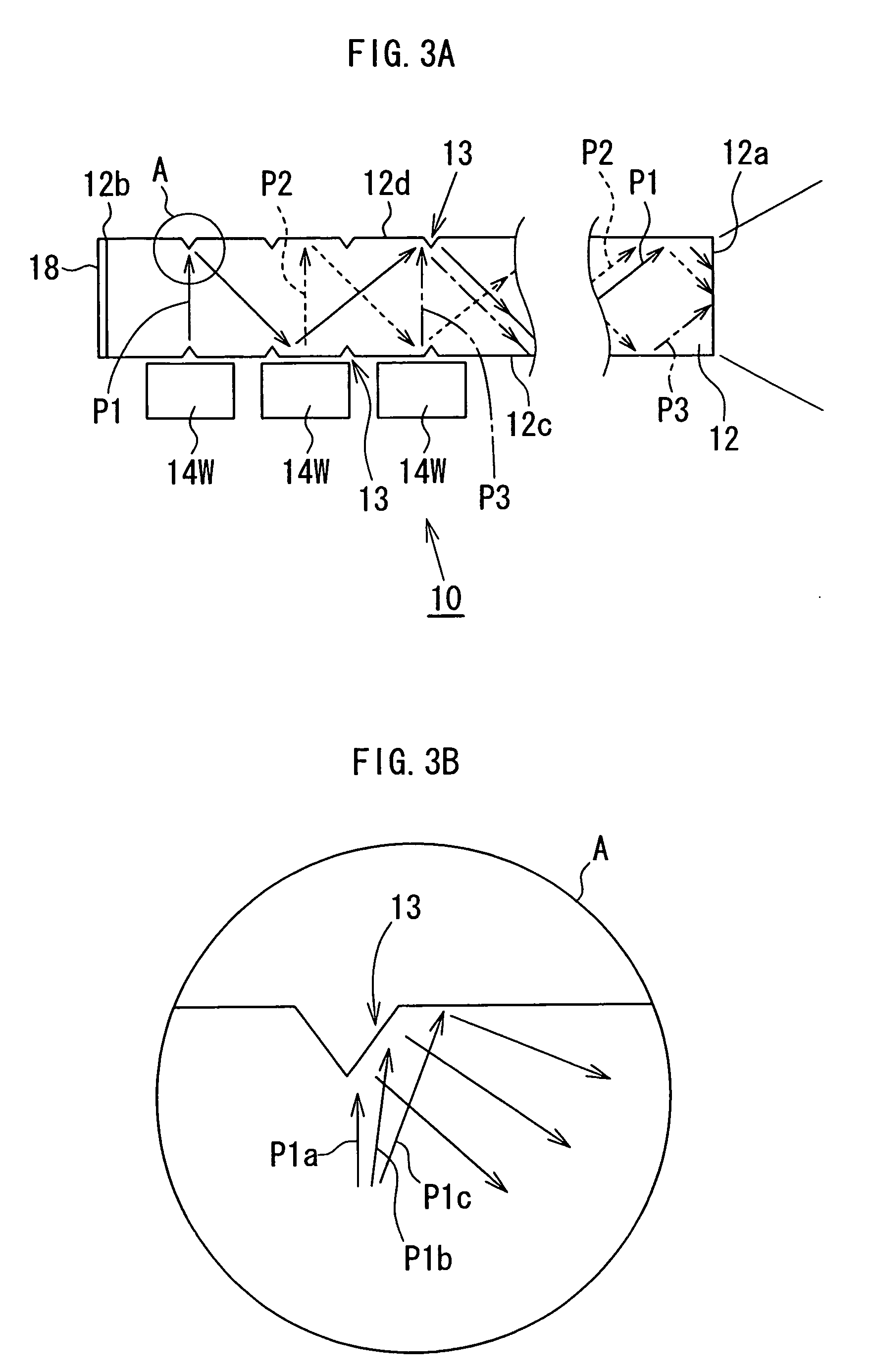
[0037] Referring to FIGS. 1A and 1B, an illuminating device 10 according to the present invention includes a light source assembly 14 composed of a plurality of point light sources 14W, and a light guide bar 12. The light guide bar 12 according to the present embodiment is a quadrangular prism formed of a transparent material, such as glass, acrylic resin or polycarbonate resin, has an optical path converting means 13 (to be described later) provided on each of side surfaces 12c and 12d thereof positioned opposite to each other, and has a light reflection means 18 disposed on one end surface 12b (hereinafter referred to as light reflection surface as appropriate) thereof. The point light sources 14W are each constituted by a white light emitting diode (hereinafter referred to as white LED as appropriate), mounted on a circuit board 16 on which a wiring pattern (not shown) to feed electric power to the point light sources 14W is formed, and are arrayed in a line parallel to the longi...

fifth embodiment

[0052] Referring to FIG. 8, an image display apparatus 50 according to the present invention includes a illumination optical system 52 incorporating the illuminating device 10 described above, a light modulating means 56 to spatially modulate light from the illumination optical system 52 based on image information, a projection optical system 58 to magnify and project light from the light modulating means 56, and a condensing optical system 56 constituted by condenser lenses 53, disposed between the illumination unit 52 and the light modulating means 56, and adapted to appropriately magnify or reduce light rays from a light exit surface 12a of the illuminating device 10 so as to irradiate the light rays onto the light modulating means 56. In the present embodiment, the light modulating means 56 is constituted by a light transmissible liquid crystal display element to control transmission / non-transmission of light on a pixel-by-pixel basis according to the image information from a dr...


PUM


Abstract

An illuminating device includes: a light guide bar having a quadrangular prism configuration, formed of a transparent material, and having an optical path converting means provided on two opposite side surfaces thereof and a light source assembly composed of a plurality of point light sources and disposed at one of the two side surfaces of the light guide bar, wherein the point light sources are arrayed along the longitudinal direction of the light guide bar with their light emitting surfaces facing the one side surface of the light guide bar. Lights from the point light sources are introduced into the light guide bar from the one side surface, propagate through the light guide bar, and exit out from one end surface of the light guide bar. Also provided is an image display apparatus which includes the above-described illuminating device, a light modulating means, and a projection optical system.

Description

BACKGROUND OF THE INVENTION [0001] 1. Field of the Invention [0002] The present invention relates to an image display apparatus, and more particularly to an illuminating device including a plurality of point light sources, and also to an image display apparatus incorporating such an illuminating device. [0003] 2. Description of the Related Art [0004] Generally, a discharge lamp, such as an ultra high-pressure mercury lamp, a metal halide lamp, a xenon lamp, and the like, is used as a light source for a projection type image display apparatus, such as a consumer data projector, a video projector, and the like (hereinafter referred to as “projector” as appropriate). FIG. 10 is a schematic view of an optical system for such a projector. A projector 100 shown in FIG. 10 includes a discharge lamp 101, a reflector 102 composed of a spheroidal mirror, a light tunnel 103 having a light entrance end 103a and a light exit end 103b, a condensing optical system 104, a light modulating means 105...

Claims


Application Information

Patent Timeline
IPC IPC(8): F21V7/04H01L33/48
CPCH04N9/3197H04N9/3152
Inventor KITAMURA, ATSUSHI
Owner MINEBEA CO LTD
Why Eureka
Try Eureka