Two-stage hall effect plasma accelerator including plasma source driven by high-frequency discharge

a plasma accelerator and plasma source technology, applied in the field of plasma accelerators, can solve the problems of deterioration in performance, increased weight undesirable from the standpoint of space systems, and the initial difficulty of single-stage hall-effect plasma accelerators subjected to high temperatures to achieve such desirable characteristics

Inactive Publication Date: 2006-12-28
JAPAN AEROSPACE EXPLORATION AGENCY
View PDF6 Cites 32 Cited by
  • Summary
  • Abstract
  • Description
  • Claims
  • Application Information

AI Technical Summary

Benefits of technology

[0060] According to a second aspect of the present invention, there is provided a space propulsion engine comprising the two-stage Hall-effect plasma accelerator set forth in the first aspect of the present invention. In this space propulsion engine, the plasma-generating gas is a propellant.
[0061] According to a third aspect of the present invention, there is provided an ion acceleration apparatus comprising the two-stage Hall-effect plasma accelerator set forth in the first aspect of the present invention. In this ion acceleration apparatus, the plasma-generating gas is an ion source.
[0062] According to a fourth aspect of the present invention, there is provided a plasma etching apparatus comprising the two-stage Hall-effect plasma accelerator set forth in the first aspect of the present invention. In this plasma etching apparatus, the plasma-generating gas is an ion source for sputtering.
[0063] According to a fifth aspect of the present invention, there is provided an ion acceleration apparatus for use on the ground, which comprises a high-frequency discharge plasma generation-based two-stage Hall-effect plasma accelerator, and a beam target. The two-stage Hall-effect plasma accelerator has an ion acceleration section, and a high-frequency wave supply section for supplying a high-frequency wave to the ion acceleration section. The ion acceleration section includes: an annular acceleration channel comprising two concentric cylindrical structures different in radius, which have a first end formed as an open end for ejecting an ion therefrom and a second, opposite, end located adjacent to the high-frequency wave supply section, and a space defined between the concentric cylindrical structures; a gas inlet port connected to the annular acceleration channel at a position adjacent to the high-frequency wave supply section to introduce a plasma-generating gas serving as an ion source, from the outside to the inside of the annular acceleration channel; an anode disposed in the space of the annular acceleration channel at a position adjacent to the high-frequency wave supply section; magnetic-field generation means for generating a magnetic field having a given intensity distribution in the radial direction from the central axis of the annular acceleration channel; and high-frequency wave generation means for generating a high-frequency wave to be introduced in the space of the annular acceleration channel. The beam target is disposed in the vicinity of the first open end of the annular acceleration channel and adapted to have an acceleration voltage to be applied at a given level with respect to the anode. Based on the above structure, the plasma-generating gas introduced from the gas inlet port into the space of the annular acceleration channel is ionized by the high-frequency wave supplied from the high-frequency wave supply section to generate plasma; a positive ion included in the generated plasma is accelerated in the space of the annular acceleration channel toward the first open end by the acceleration voltage applied between the anode and the beam target, and ejected toward the beam target; and an electron included in the generated plasma is restricted in its movement in the axial direction of the concentric cylindrical structures by an interaction with the radial magnetic field. Further, the high-frequency wave supply section includes high-frequency wave introduction means for introducing the high-frequency wave generated by the high-frequency wave generation means, into the space of the annular acceleration channel. In the ion acceleration apparatus, the ion acceleration section is operable to control a degree of the ion acceleration in accordance with the acceleration voltage serving as an acceleration control parameter, and the high-frequency wave supply section is operable to control an amount of the plasma generation in accordance with the high-frequency wave output serving as a plasma-generation control parameter to be controlled independently of the acceleration control parameter.
[0064] According to a sixth aspect of the present invention, there is provided a p

Problems solved by technology

The objective of producing the above optimal magnetic field (magnetic flux) cannot be achieved without using a complicated structure in a magnetic circuit, electromagnetic coil, magnet, magnetic shielding (magnetic screen) and/or magnetic shunt device, which leads to increase in weight undesirable from the standpoint of a space system.
Moreover, a magnetic-field based system is liable to cause deterioration in performance due to temperature rise.
The single-stage Hall-effect plasma accelerator to be subjected to high temperatures originally has difficulties in achieving such desirable characteristics.
All of these inventions relates to a magnetic-field design, but cannot fundamentally solve the difficulties in the magnetic-field design.
Thus, it is difficult to control the power distribution in an active manner.
This makes it difficult to control the Hall-effect plasma accelerator to be an optimal operational state capable of achieving an efficient operation
Further, in the single-stage Hall-effect plasma accelerators, the plasma generation and the ion acceleration are successively performed, and thereby the ratio between the plasma generation and the ion

Method used


Image

  • Two-stage hall effect plasma accelerator including plasma source driven by high-frequency discharge
  • Two-stage hall effect plasma accelerator including plasma source driven by high-frequency discharge
  • Two-stage hall effect plasma accelerator including plasma source driven by high-frequency discharge

Examples


Embodiment Construction

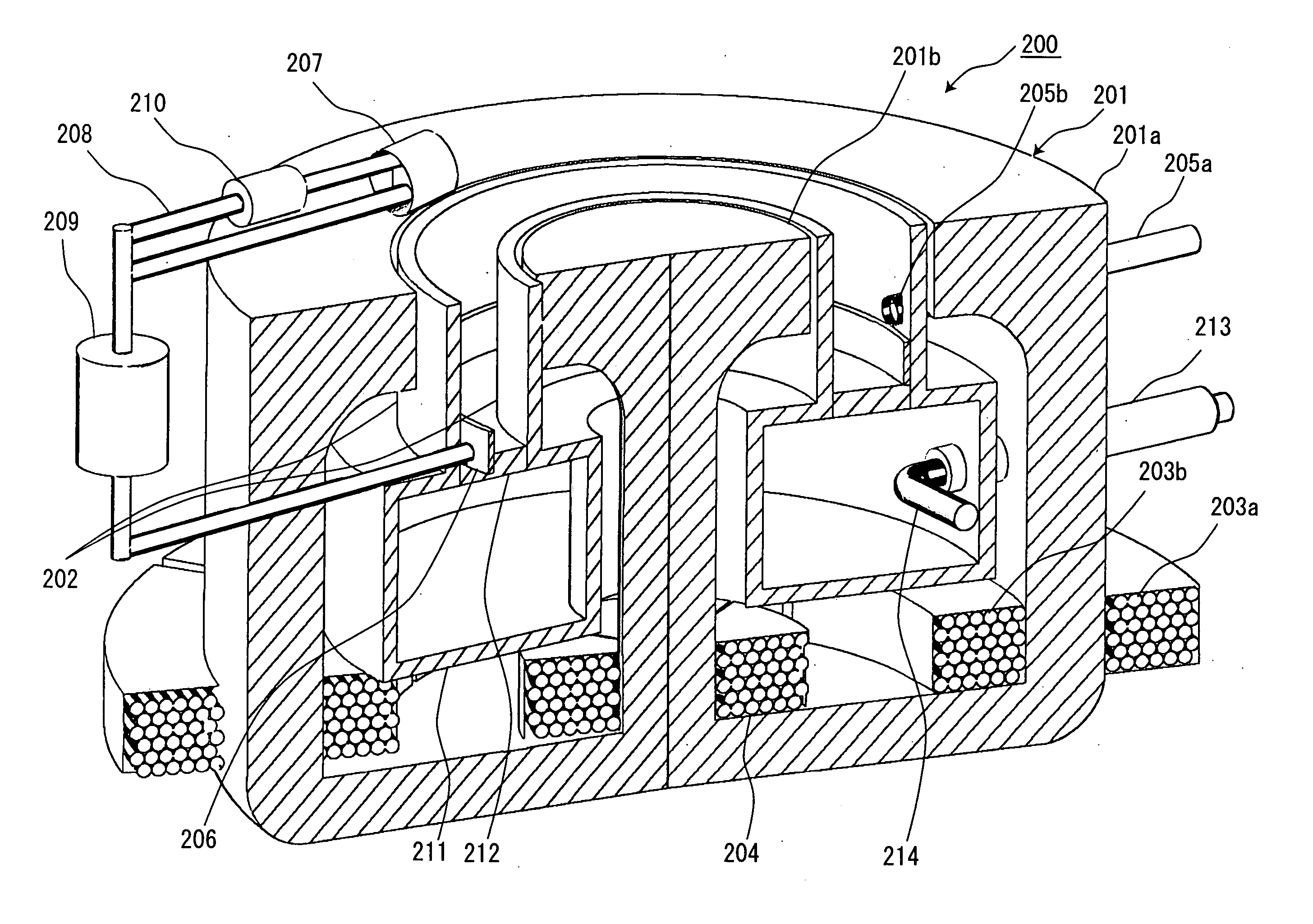
[0135] With reference to the drawings, a high-frequency discharge plasma generation-based two-stage Hall-effect plasma accelerator 200 according to one embodiment of the present invention (hereinafter referred to as “two-stage Hall-effect plasma accelerator 200” for brevity) will now be described.

[0136]FIG. 4 is a partially cutaway perspective sectional view showing the structure of the two-stage Hall-effect plasma accelerator 200. FIG. 7 is a combinational diagram of an electric circuit and a schematic section of the two-stage Hall-effect plasma accelerator 200. The two-stage Hall-effect plasma accelerator 200 comprises a pole piece 201, an acceleration channel 202, a coil 203a, a coil 203b, a coil 204, a propellant feed port 205a, a propellant discharge port 205b, an anode 206, a cathode 207, a wiring 208, an acceleration power source 209, a neutralizer power source 210, a cavity resonator 211, a high-frequency wave transmitting window portion 212, a waveguide 213, a high-frequen...


PUM


Abstract

Disclosed is a high-frequency discharge plasma generation-based two-stage Hall-effect plasma accelerator, which comprises an annular acceleration channel having a gas inlet port, a high-frequency wave supply section, an anode, a cathode, a neutralizing electron generation portion and a magnetic-field generation means, wherein: gas introduced from the gas inlet port into the annular acceleration channel is ionized by a high-frequency wave supplied from the high-frequency wave supply section, to generate plasma; a positive ion includes in the generated plasma is accelerated by an acceleration voltage applied between the anode and cathode, and ejected outside; and an electron included in the generated plasma is restricted in its movement in the axial direction of the annular acceleration channel by an interaction with a magnetic field. The two-stage Hall-effect plasma accelerator is designed to control a degree of ion acceleration in accordance with the acceleration voltage serving as an acceleration control parameter, and control an amount of plasma generation in accordance with the high-frequency wave output serving as a plasma-generation control parameter. The two-stage Hall-effect plasma accelerator of the present invention can control the ion acceleration and the plasma generation in a highly independent manner.

Description

BACKGROUND OF THE INVENTION [0001] 1. Technical Field [0002] The present invention relates to a plasma accelerator, and more particularly to a two-stage Hall-effect plasma accelerator, and various apparatuses using the same, such as a space propulsion engine, an ion acceleration apparatus and a plasma etching apparatus. [0003] 2. Description of the Background Art [0004] As one type of electric propulsion rockets adapted to be used as a space propulsion engine, there has been known a Hall-effect accelerator developed mainly in the former Soviet Union. The Hall-effect plasma accelerator comprises an annular acceleration channel and a mechanism for applying a magnetic field and an electric field, respectively, in the radial and axial directions of the annular acceleration channel. A cathode for emitting electrons is disposed in the vicinity of the downstream end (outlet or open end) of the annular acceleration channel, and an anode is disposed at the upstream end (opposite end of the o...

Claims


Application Information

Patent Timeline
IPC IPC(8): H01J7/24
CPCF03H1/0075H05H1/54H01J27/18
Inventor KUNINAKA, HITOSHI
Owner JAPAN AEROSPACE EXPLORATION AGENCY
Why Eureka
Try Eureka