Electro-optical focal plane array digital sensor system

a digital sensor and optical focal plane technology, applied in the field of laser beam detection and tracking, can solve the problems of affecting the smoothness of the tracking system, increasing the size, weight, power, thermal control, complexity, etc., and achieve the effect of increasing the frame rate pixel data

Active Publication Date: 2007-01-11
THE AEROSPACE CORPORATION
View PDF3 Cites 30 Cited by
  • Summary
  • Abstract
  • Description
  • Claims
  • Application Information

AI Technical Summary

Benefits of technology

[0014] Another object of the invention is to provide a system for determining a window of interest encompassing a spot of a laser beam impinging on a focal plane array for increase frame rates pixel data from the focal plane array.

Problems solved by technology

This motion is laser jitter and disadvantageously affects the ability of a tracking system to smoothly track the laser beam source.
The cited patents teach software and logic resources required for the acquisition sensor to cue the tracking sensor while incurring increased system size, weight, power, thermal control, and complexity.
The optical components are sensitive to space radiation and thermal environments, suffer aging effects, maintaining mechanical alignment and calibration is critical.
There are critical problems with the teachings of the cited references.
The operational limitations and shortfalls are due to slow signal processing and the obtainable precision of the pointing commands that the signal processing system uses to generate for the pointing commands.
Slow signal processing time and inadequately low pointing resolution of the generated pointing commands are problems of the closed-loop system response.
This overall response time is too slow and as such, will not accommodate the requirements of advanced imaging sensors.
Another problem is that the prior systems do not implement an efficient and optimal use of the imaging sensor built-in and primary operating feature.
As such, the scanning limits system response time.
Another problem with prior system is the use of quadrature photodetector cells as an imaging sensor, be it for either for laser detection, acquisition or tracking functions.
These quadrature photodetector cells devices offer a very limited small field-of-views in terms of how much space the sensor can scan through at any given time and the outputs from these quadrature photodetector cells devices are error signals.
Error signals only provide the signal processor with limited data in which even further processing is required, which then allows a less precise coarse laser tracking function.
A drawback to a quad cell implementation is a highly restricted field of view for the four cell quadrant detectors.
Precise optical alignment between the sensor and laser beam line-of-sight is not always achievable.
However, only a few of the publications consider the application of these devices to spacecraft or space-borne systems.
The reason appears to be the susceptibility of visible bandwidth CMOS focal plane array devices to total dose ionizing radiation damage, as well as proton displacement damage resulting in increased photodiode dark current.
The systems of the cited references disadvantageously require multiple sensors and processors, require sensor data pre-formatting and processing, have sensor limited field-of-view and poor output data, have slow millisecond pointing responses, have low pointing resolution in milliradians, do not process data in near-real time, require additional processing for laser jitter mitigation, are unable to reprogram internal sensor operations in near-real time, and require costly and complex optical technologies.

Method used


Image

  • Electro-optical focal plane array digital sensor system
  • Electro-optical focal plane array digital sensor system
  • Electro-optical focal plane array digital sensor system

Examples


Embodiment Construction

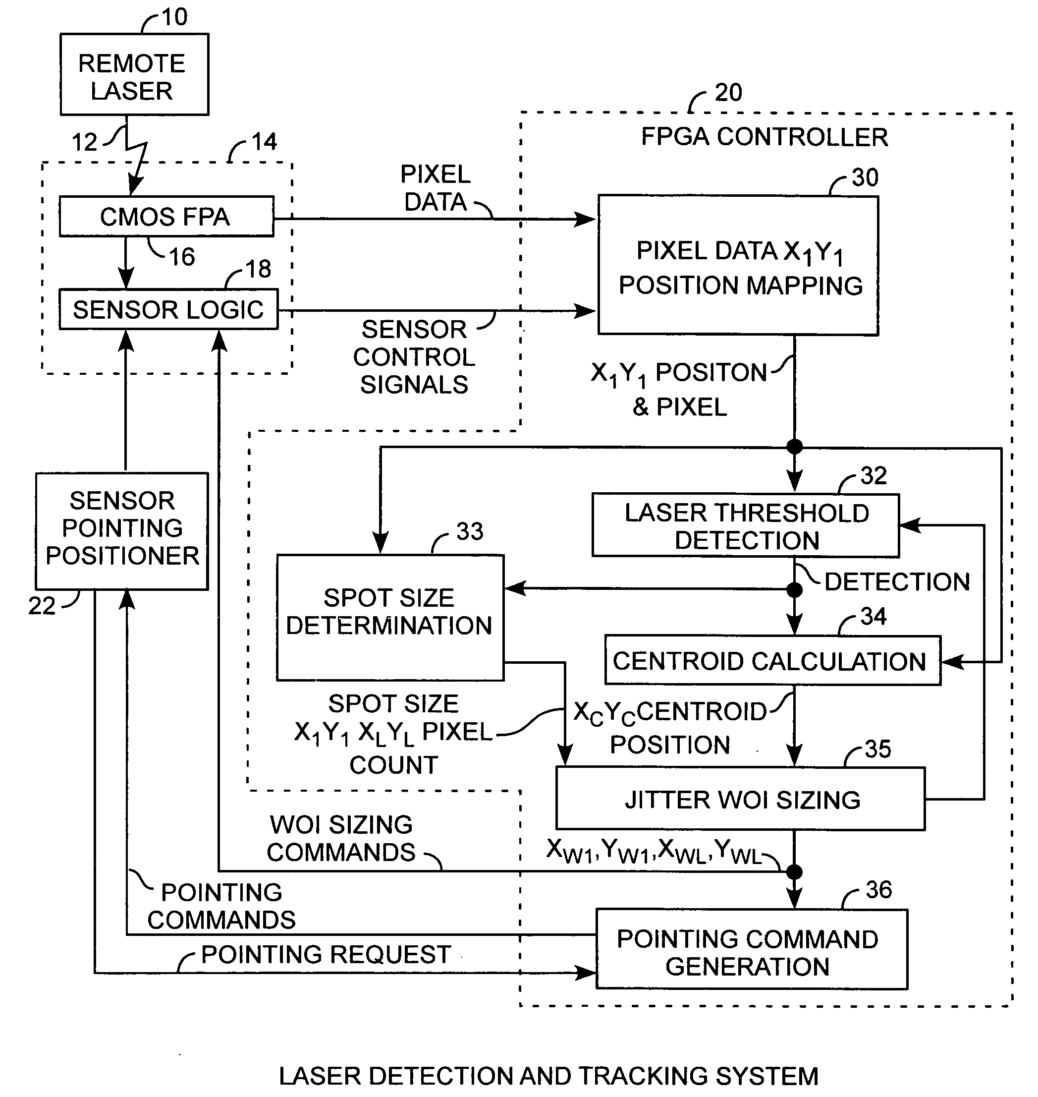
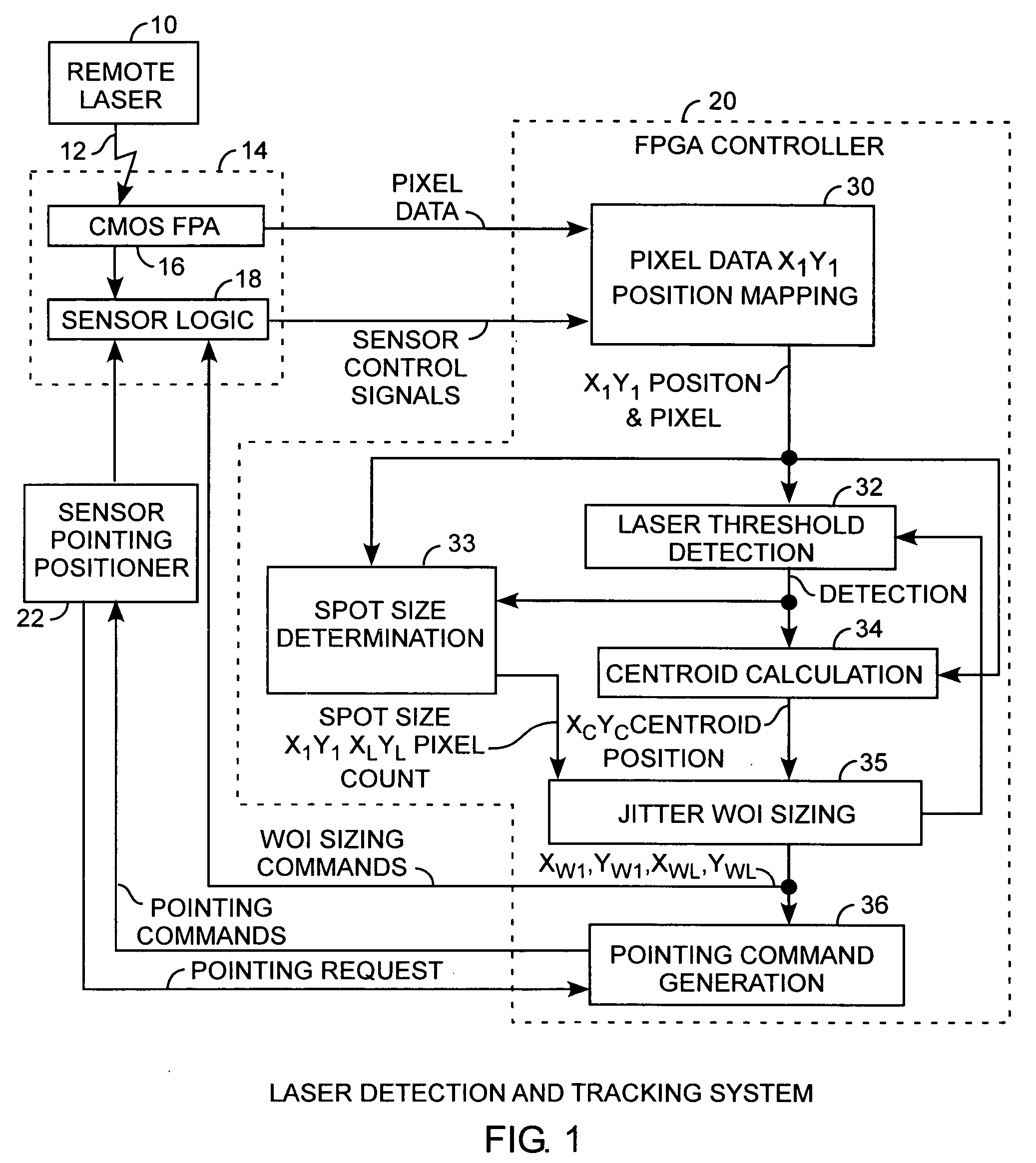
[0022] An embodiment of the invention is described with reference to the figures using reference designations as shown in the figures. Referring to the Figures, a laser detection and tracking system is used to track a remote laser 10 as a source of a laser beam 12. The laser 10 may be disposed on an orbiting satellite and the laser detection and tracking system may reside in a ground tracking station or a second satellite. The laser beam 12 impinges upon a focal plane array (FPA) sensor 14 including a CMOS focal plane array 16 and sensor logic 18 for respectively communicating pixel data and control signals to a controller 20 that is preferably a field programmable gate array (FPGA). The controller 20 functions as a window controller for the sensor 14. The sensor 14 may be a satellite or ground station electro-optical sensor used to detect and continuously track the laser beam 12. The gate array controller 20 can be configured using VHSIC hardware description languages for embedded ...


PUM


Abstract

A laser beam detection and tracking system includes a focal plane array sensor providing pixel data and a field programmable gate array controller receiving the pixel data for determining a centroid of the illuminating spot of the impinging laser beam and for determining variably sized windows of interest disposed around the spot for selecting a subset of pixels of the array for communicating a subset of the pixel of a window frame of data from the array to the controller for increasing the array frame rate for reducing laser jitter during tracking of the beam for improved beam tracking performance.

Description

FIELD OF THE INVENTION [0001] The invention relates to the field of laser beam detection and tracking. More particularly, the invention relates to processing pixel data from a focal plane array receiving a laser beam that can be a satellite laser light beam that is tracked by a tracking system for keeping the laser beam within the focal plane array. BACKGROUND OF THE INVENTION [0002] Space-based laser communication systems establish and maintain constant spatial orientation between satellites for providing a continuous closed-loop communications link. A ground system will search for a space system initiating a laser communication link with the ground system. The space system directs a laser beam at an electro-optical focal plane array sensor of the ground system. A focal plane array is known as an imaging sensor. A detected pixel is a pixel having a magnitude value of pixel data exceeding a detection threshold level. The pixel data is a decimal value of the magnitude of the impingin...

Claims


Application Information

Patent Timeline
Patent Type & Authority Applications(United States)
IPC IPC(8): G01J1/42
CPCG01J1/4257G01J1/4228
Inventor MAKSYMOWICZ, JOHN
Owner THE AEROSPACE CORPORATION
Why Eureka
Try Eureka