The
clock speed of a typical data or
address bus, on the other hand, is limited by the impedance and other physical characteristics of conductive traces that comprise the
bus.
Thus, it is often times impractical to run these buses at a higher speed to match the speed of the fast CPU due to issues related to power, interference, and the like.
Together, these factors tend to limit the speed of a typical
DRAM to well below the
operating speed of the CPU.
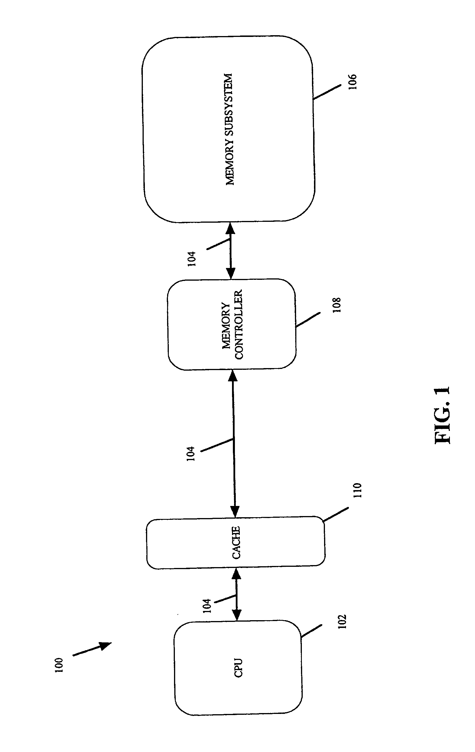
Caching, however, increases the overall complexity of the computer system architecture and its
operating system.
Further, the use of expensive and power-hungry cache memory (e.g., on-board high speed custom SRAM) disadvantageously increases cost,
power consumption, and the like.
If the
cache hit rate is low, there may not be a significant improvement in memory access speed to justify the added complexity and cost of a cache subsystem.
Modern complex
software, which is often employed to manipulate large
database,
graphics, sound, or video files, requires a large amount of main memory space for optimum performance.
Due to
power consumption, board space usage, and cost concerns, however, most computer systems are however manufactured and sold today with a less-than-optimum amount of physical memory
on board.
Consequently, the overall system performance suffers.
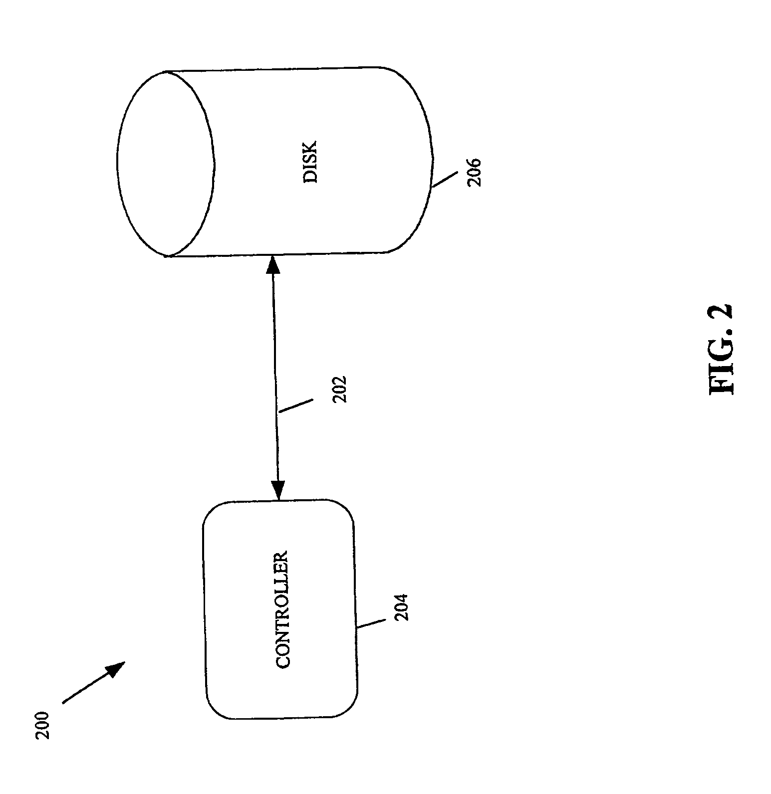
When a hard disk drive is employed for storing data, for example, the limited speed of the data transmission link between the hard disk drive and the main
system bus, the slow
access time due to the mechanical rotation nature of the hard disk's platters and the mechanical movement of the
actuator arm that contains the read / write head, as well as the fixed storage capacity of the platters all represent factors that tend to limit system performance.
The data
transmission bandwidth bottleneck also exists within modern high-speed computer networks, which are widely employed for carrying data among networked devices, whether across a room or across a continent.
In these devices, the line cards and / or switch fabric are configured to operate at a fixed speed, which is typically limited by the speed of the constituent devices comprising the
line card.
In some cases, the
bottleneck may be with the protocol employed to transmit the data among the various networked devices.
Accordingly, even if the transmission media itself (such as a
fiber optic) may theoretically be capable of carrying a greater amount of data, the hardware,
software, and transmission protocols may impose a hard limit on the amount of data carried between two nodes in a
computer network.
A hardware
upgrade to one of the higher speed protocols, unfortunately, tends to involve network-wide disruptive changes (since the sending and receiving network nodes must be upgraded to operate at the same speed).
A system-wide
upgrade is also costly as many network nodes and components must be upgraded simultaneously to physically
handle the higher speed protocol.
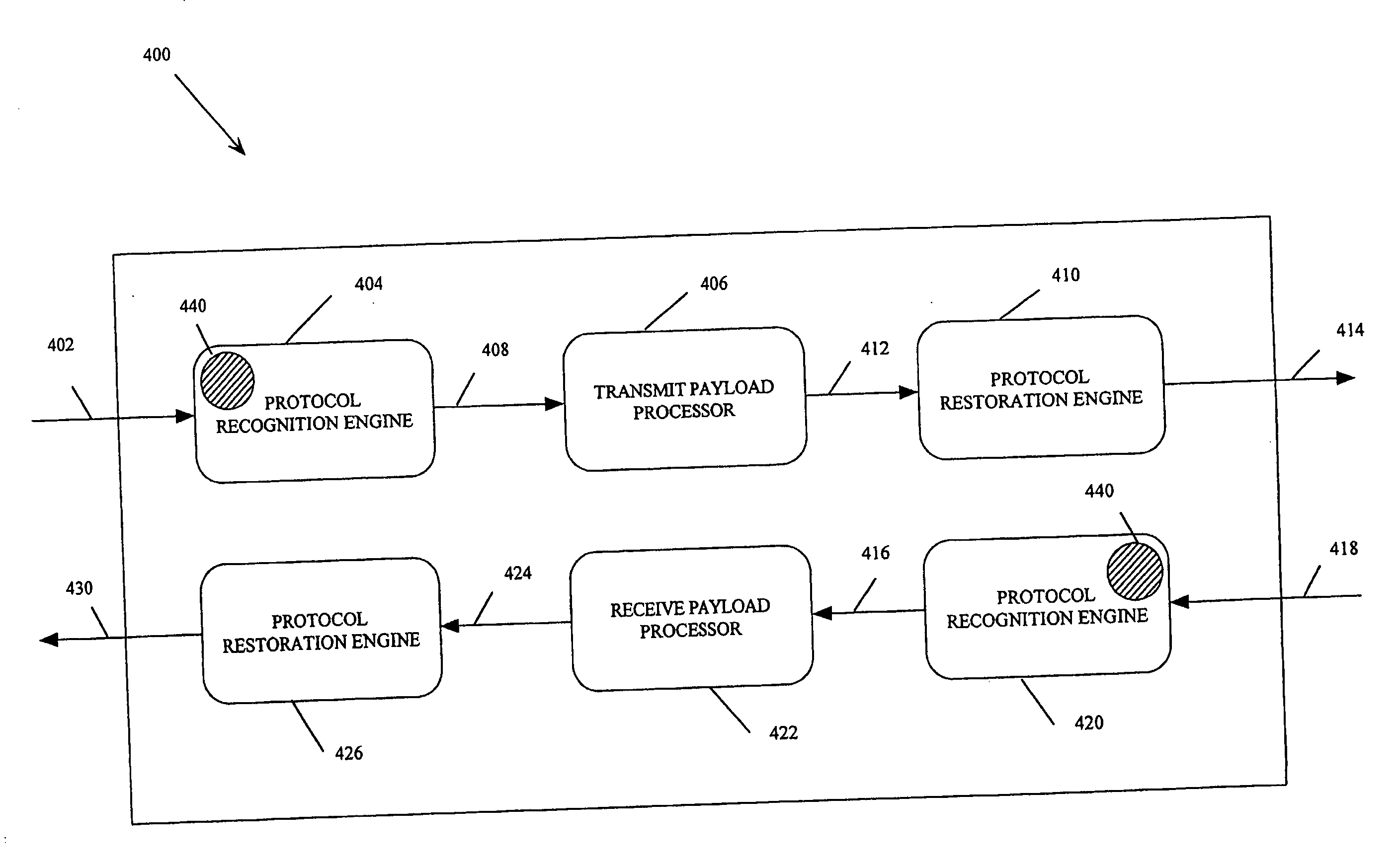
As mentioned, some incoming data frames may be non-optimizable, e.g., due to an explicit request from
software or from some other higher layer in the communication stack.

