
Turbine housing and floatation assembly

Inactive Publication Date: 2007-01-25
US ISIDRO U
View PDF7 Cites 52 Cited by
  • Summary
  • Abstract
  • Description
  • Claims
  • Application Information

AI Technical Summary

Benefits of technology

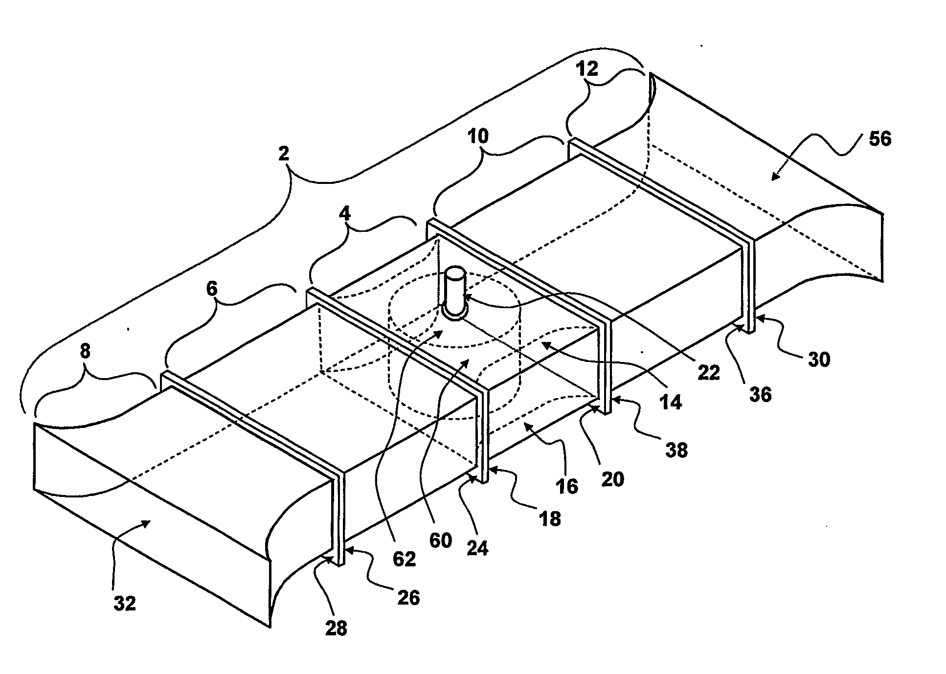
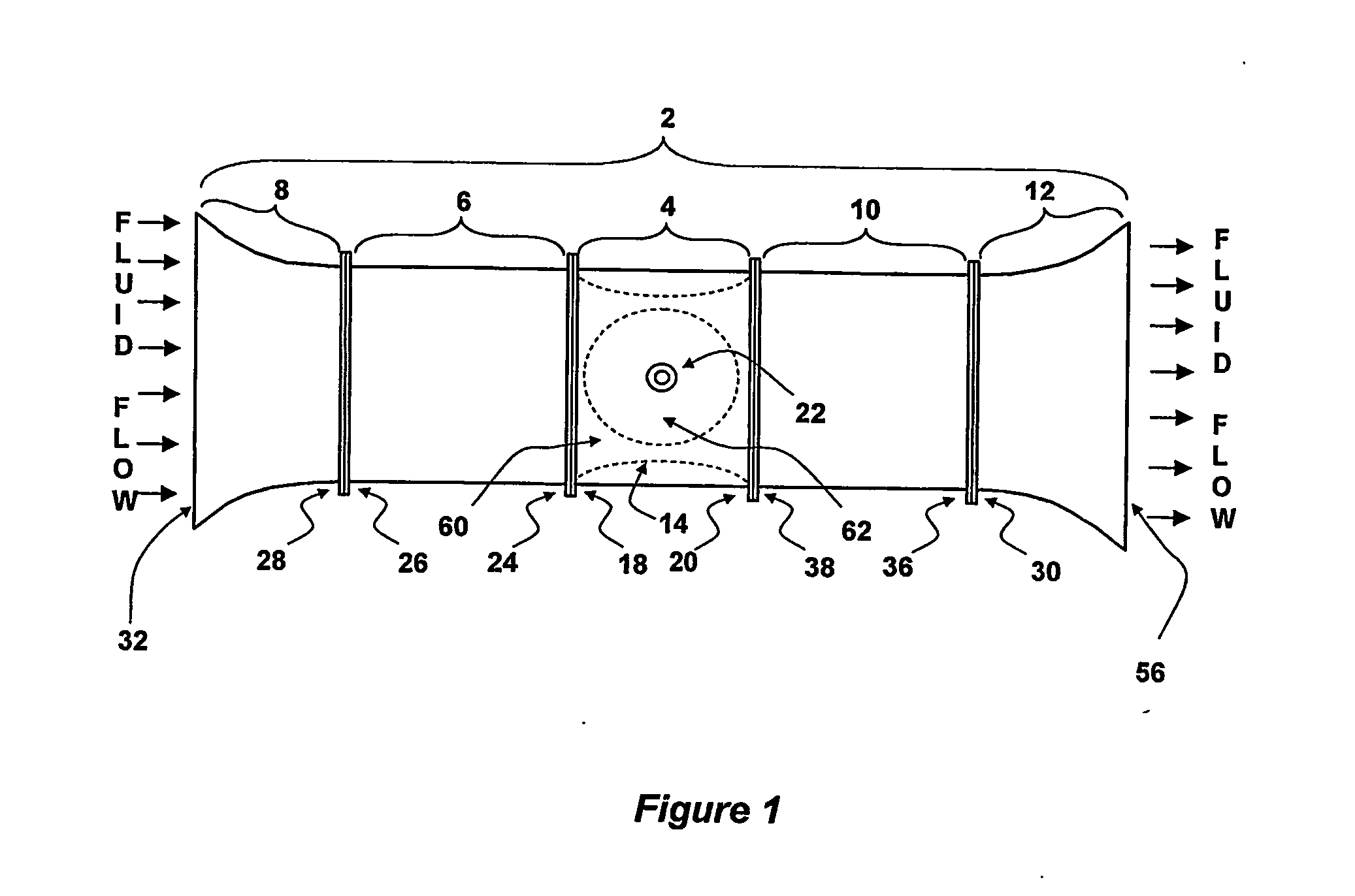
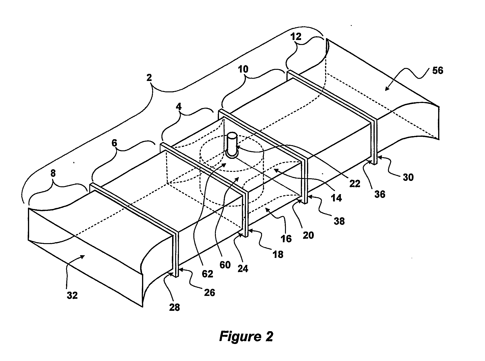
[0023] As the fluid comes out of the venturi's throat, the increasing cross-sectional size from the central portion of the bore to the larger cross-sectional size of the bore at the second end causes the fluid to reduce in speed. The fluid is then deliverd to the conducting duct portion of the other side to stabilize the fluid speed. As the fluid enter and progresses inside the adjoining outlet portion, the slowly increasing area of the outlet portion further reduces the speed to a slightly lower speed than the outside main stream fluid speed, this allows the main stream to suck the fluid coming out of the whole housing.
[0041] To hold the turbine housing and floatation unit at approximately the same location in the area, steel chains / cables with calculated slack are preferably attached to at least two anchors located at two different positions on the seabed. Attached to the fore is at least one anchor chain / cable, aft of the turbine housing and floatation assembly the other anchor chain / cable is / are attached. Thus the turbine housing and floatation assembly is preferably tethered at both fore and aft and is allowed to move forward or backward only depending on the direction of the tide flow and is prevented to turn around, dictated by the cable / s slack, to avoid fouling of the electrical cables. Thus, the opening of the turbine housing will preferably be facing against the flow of the fluid and will be self adjusting in relation with the fluid flow, regardless of where the fluid flow is coming from.

Problems solved by technology

Traditional sources of generating power such as the combustion of fossil fuels, including coal, natural gas and oil, are becoming less and less favored due to their environmental disadvantages.
The combustion of coal, oil or gas generates large quantities of carbon dioxide, oxides of sulfur and nitrogen, and other pollutant gases, which may contribute to global warming, acid rain, air pollution and a number of other environment and health damaging effects.
World reserve of coal, oil and natural gas are also thought to be relatively low, and may run out in the foreseeable future.
Unfortunately, the use of radioactive materials means that environmentally safe methods of disposal of waste are difficult to achieve.
There have been many occurrences of radioactive waste leaking from these containers and damaging the local environment.
The damage caused by radioactive waste may be irreversible and the radiation generated by the waste may last decades.
Thus, eliminating the counter-rotative forces produces dramatic increase in power output.
Machines operating in the open seas are subjected to extreme environmental weather conditions.
Thus, because of these considerations, widespread use of the open sea for power extraction becomes prohibitive.

Method used


Image

  • Turbine housing and floatation assembly
  • Turbine housing and floatation assembly
  • Turbine housing and floatation assembly

Examples


second embodiment

[0066] Referring now to FIGS. 3 and 4, the turbine housing 2, includes all the elements of the embodiment described for FIGS. 1 and 2, but also includes means to manage the fluid flow entering the turbine housing portion 4, in the foprm of fluid flow restriction means in the form of plates 34 and 40 installed inside the conducting duct portions 6 and 10. The fluid flow restriction means 34 and 40 are either straight rectangular plates, or are curvelinear plates, shaped to form a smooth curvature to guide, increase the speed, and direct the flow of the fluid. When the inlet portion 8 opening 32 is facing the fluid flow, the entering fluid increases in speed as it passes through the narrowing space of the bore of the inlet portion 8. The fluid enters the conducting unit 6, passing along the outward face 90 of the plate 34, the fluid speed increases further and is directed to hit the blades / buckets of turbine 62 where it is most needed, to produce optimum power extraction. Afterwards, ...

third embodiment

[0073] Referring now to FIGS. 5, 6, 7, and 8, the turbine housing 2 of the invention, includes all elements described in FIGS. 3 and 4, but include floatation assembly 80 to make the turbine housing 2 float. The floatation assembly 80, is composed of at least one floatation unit 82, preferably, at least two floatation units 82, separated by superstructure and flooring 84, such that when the two floatation units 82 are bolted and joined, the turbine housing 2, will be mounted to straddle the floatation assembly80, sandwiching the whole body lengthwise. When bolted to the superstructure and flooring 84, the turbine housing 2 becomes an integral unit of the turbine housing and floatation assembly 94. Mounting is made such that, the turbine housing 2 is lower than the top of the superstructure and flooring 84, suitably to make it totally underwater while the super structure and flooring 84 is well above the water.

[0074] On top of the superstructure and flooring 84 is where the turbine g...

fourth embodiment

[0077] Referring now to FIGS. 8 and 9, the invention includes all the elements of the embodiment described for FIGS. 5, 6, 7, and 8, but includes means to submerge the whole turbine housing and floatation assembly 94 to continuously operate; this time under the surface of the water.

[0078] At least one mechanically / electrically or pneumatically controlled discharge valve 72 and at least one mechanically / electrically or pneumatically controlled charging valve 74 is installed on the top surface of the floatation unit 82.

[0079] In use, during normal operating condition, except for the flooring 84, the rest of the floatation means assembly 80 is submerged under the water surface.

[0080] During bad weather condition water surface becomes rough. The continuously buffeting disturbances cause by the waves, disrupts the smooth operation of the system. To avoid the possibility of a mooring break or destruction, the whole turbine housing and floatation assembly 94 is required to submerge to a ...


PUM


Abstract

The invention relates to a turbine housing comprising a housing (2) body having a first end (8), second end (12) and a central region (4), wherein the housing body comprises a bore running therethrough, and wherein the bore tapers from a first larger cross-section at and / or in the region of the first and second ends to a second, smaller cross-section towards the central region. The turbine housing may also include a fluid flow restriction means arranged (34, 40) in use to restrict fluid speed, direction or location within the turbine housing.

Description

TECHNICAL FIELD OF THE INVENTION [0001] This invention relates to turbine housings and to power enhancement of prime movers, and in particular to prime movers which harness energy from free flowing fluid. The invention also extends to a method of increasing generated energy of prime movers. BACKGROUND TO THE INVENTION [0002] Renewable and non-polluting sources of energy are currently in high demand. Traditional sources of generating power such as the combustion of fossil fuels, including coal, natural gas and oil, are becoming less and less favored due to their environmental disadvantages. The combustion of coal, oil or gas generates large quantities of carbon dioxide, oxides of sulfur and nitrogen, and other pollutant gases, which may contribute to global warming, acid rain, air pollution and a number of other environment and health damaging effects. World reserve of coal, oil and natural gas are also thought to be relatively low, and may run out in the foreseeable future. [0003] O...

Claims


Application Information

Patent Timeline
IPC IPC(8): F01D25/28F03B13/26F03B17/06
CPCF03B13/264F03B17/062F03B17/063F05B2240/12F05B2240/13Y02E10/28F05B2240/932F05B2240/97F05B2250/323F05B2250/324F05B2250/50F05B2240/14Y02E10/30Y02E10/20
Inventor URSUA, ISIDRO U.
Owner US ISIDRO U
Learn More