Discharge produced plasma EUV light source

a plasma euv light source and discharge-produced technology, applied in the field of euv and softxray light sources, can solve the problems of high thermal load on components, electrode lifetime is another euv light source issue that needs attention, and several detrimental effects on performance and component li

Inactive Publication Date: 2007-02-01
ASML NETHERLANDS BV +1
View PDF99 Cites 27 Cited by
  • Summary
  • Abstract
  • Description
  • Claims
  • Application Information

AI Technical Summary

Benefits of technology

[0013] A DPP EUV source is disclosed which may comprise a debris mitigation apparatus employing a metal halogen gas producing a metal halide from debris exiting the plasma. The EUV source may have a debris shield that may comprise a plurality of curvilinear shield members having inner and outer surfaces connected by light passages aligned to a focal point, which shield members may be alternated with open spaces between them and may have surfaces that form a circle in one axis of rotation and an ellipse in another. The electrodes may be supplied with a discharge pulse shaped to produce a modest current during the axial run out phase of the discharge and a peak occurring during the radial compression phase of the discharge. The light source may comprise a turbomolecular pump having an inlet connected to the generation chamber and operable to preferentially pump more of the source gas than the buffer gas from the chamber. The source may comprise a tuned electrically conductive electrode comprising: a differentially doped ceramic material doped in a first region to at least select electrical conductivity and in a second region at least to select thermal conductivity. The first region may be at

Problems solved by technology

A consequence of EUV light generation is high thermal loads on components close to the EUV source point.
Electrode lifetime is another EUV light source issue that needs attention.
This can lead to several detrimental effects on performance and on component life, e.g., in the case of the central electrode, thermal loads may be so severe that the outer surface of the electrode could excessively erode, e.g., through material vaporization.
Erosion eventually forces replacement of the electrode for a number of reasons, including

Method used


Image

  • Discharge produced plasma EUV light source
  • Discharge produced plasma EUV light source
  • Discharge produced plasma EUV light source

Examples


Embodiment Construction

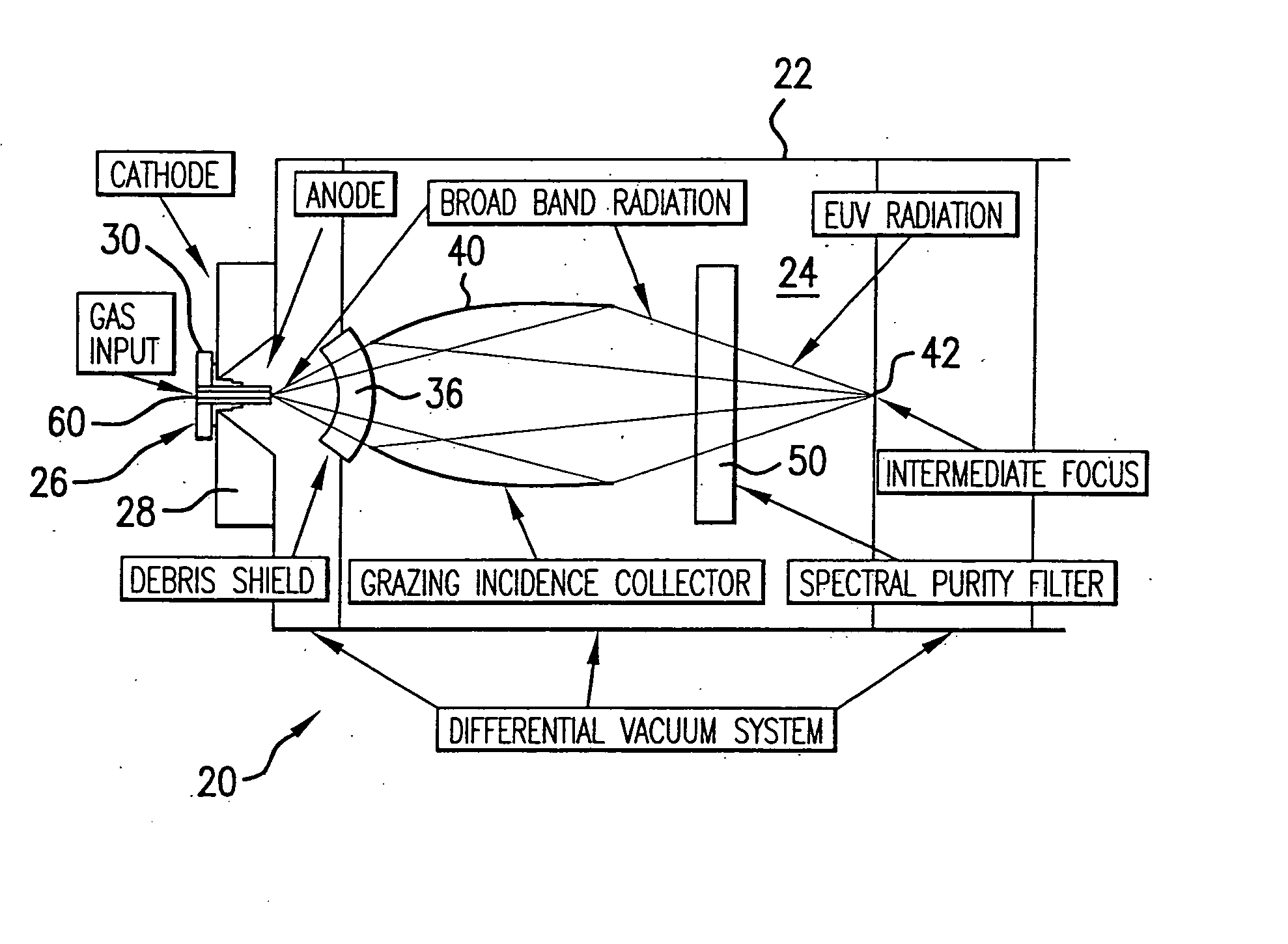
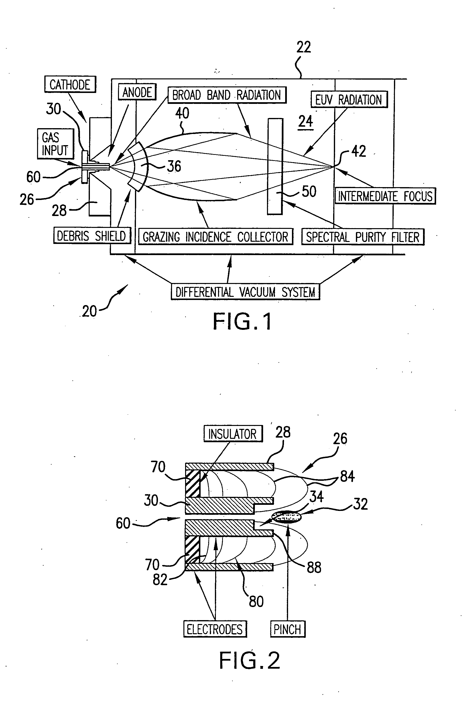
[0033] Turning now to FIG. 1 there is shown a discharge produced plasma (“DPP”) EUV and soft-x-ray light source 20 according to an embodiment of the present invention. The EUV light source may include, e.g., a housing 22, defining a discharge chamber 24. Attached, e.g., through a sealed opening in one wall of the chamber 22 may be, e.g., a pair of electrodes 26, which may include, e.g., generally cylindrical electrodes including, e.g., an outer electrode 28, which may be, e.g., the cathode, and an inner electrode 30, which may be, e.g., an anode or vice-versa, but for purposes of this disclosure the former designations will be used. The inner electrode 30 may be insulated from the outer electrode 28, e.g., by an insulator 70 as shown in FIG. 2, and together, when supplied by a very high voltage and with a very fast rise time pulse of electrical energy, e.g., from a solid state pulse power module 139, shown in FIG. 7, produce a discharge between the electrodes 28, 30, e.g., through a...


PUM


Abstract

An DPP EUV source is disclosed which may comprise a debris mitigation apparatus employing a metal halogen gas producing a metal halide from debris exiting the plasma. The EUV source may have a debris shield that may comprise a plurality of curvilinear shield members having inner and outer surfaces connected by light passages aligned to a focal point, which shield members may be alternated with open spaces between them and may have surfaces that form a circle in one axis of rotation and an ellipse in another. The electrodes may be supplied with a discharge pulse shaped to produce a modest current during the axial run out phase of the discharge and a peak occurring during the radial compression phase of the discharge. The light source may comprise a turbomolecular pump having an inlet connected to the generation chamber and operable to preferentially pump more of the source gas than the buffer gas from the chamber. The source may comprise a tuned electrically conductive electrode comprising: a differentially doped ceramic material doped in a first region to at least select electrical conductivity and in a second region at least to select thermal conductivity. The first region may be at or near the outer surface of the electrode structure and the ceramic material may be SiC or alumina and the dopant is BN or a metal oxide, including SiO or TiO2. The source may comprise a moveable electrode assembly mount operative to move the electrode assembly mount from a replacement position to an operating position, with the moveable mount on a bellows. The source may have a temperature control mechanism operatively connected to the collector and operative to regulate the temperature of the respective shell members to maintain a temperature related geometry optimizing the glancing angle of incidence reflections from the respective shell members, or a mechanical positioner to position the shell members. The shells may be biased with a voltage. The debris shield may be fabricated using off focus laser radiation. The anode may be cooled with a hollow interior defining two coolant passages or porous metal defining the passages. The debris shield may be formed of pluralities of large, intermediate and small fins attached either to a mounting ring or hub or to each other with interlocking tabs that provide uniform separation and strengthening and do not block any significant amount of light.

Description

RELATED APPLICATIONS [0001] This application is a divisional of U.S. Ser. No. 10 / 742,233 filed Dec. 18, 2003, which is a continuation-in-part of U.S. Ser. No. 10 / 409,254 filed Apr. 8, 2003, now U.S. Pat. No. 6,972,421, which is a continuation-in-part of U.S. Ser. No. 10 / 384,967 filed Mar. 8, 2003, now U.S. Pat. No. 6,904,073, U.S. Ser. No. 10 / 189,824 filed Jul. 3, 2002, now U.S. Pat. No. 6,815,700, U.S. Ser. No. 10 / 120,655 filed Apr. 10, 2002, now U.S. Pat. No. 6,744,060, U.S. Ser. No. 09 / 875,719 filed Jun. 6, 2001 now U.S. Pat. No. 6,586,757 and U.S. Ser. No. 09 / 875,721 filed Jun. 6, 2001, now U.S. Pat. No. 6,566,668, U.S. Ser. No. 09 / 690,084 filed Oct. 16, 2000, now U.S. Pat. No. 6,566,667; and claims the benefit of patent application Ser. Nos. 60 / 422,808 filed Oct. 31, 2002 and 60 / 419,805 filed Oct. 18, 2002; all of which is incorporated by reference herein.FIELD OF THE INVENTION [0002] The present invention relates to EUV and soft-x-ray light sources utilizing a discharge betwee...

Claims


Application Information

Patent Timeline
IPC IPC(8): G01J3/10G01JG03F7/20H01J1/52H01S3/00H01S3/225H05G2/00H05H1/06
CPCB82Y10/00H05G2/005G03F7/70166G03F7/70175G03F7/70825G03F7/70891G03F7/70908G03F7/70916G21K1/06G21K2201/064G21K2201/067H01S3/005H01S3/225H05G2/003H05H1/06G03F7/70033
Inventor FOMENKOV, IGOR V.PARTLO, WILLIAM N.BLUMENSTOCK, GERRY M.BOWERING, NORTBERTOLIVER, I. ROGERPAN, XIAOJIANGSIMMONS, RODNEY D.
Owner ASML NETHERLANDS BV
Why Eureka
Try Eureka