

Quinoline copolymer having branced structure and organic electroluminescent device employing same
- Summary
- Abstract
- Description
- Claims
- Application Information
AI Technical Summary
Benefits of technology
Problems solved by technology
Method used
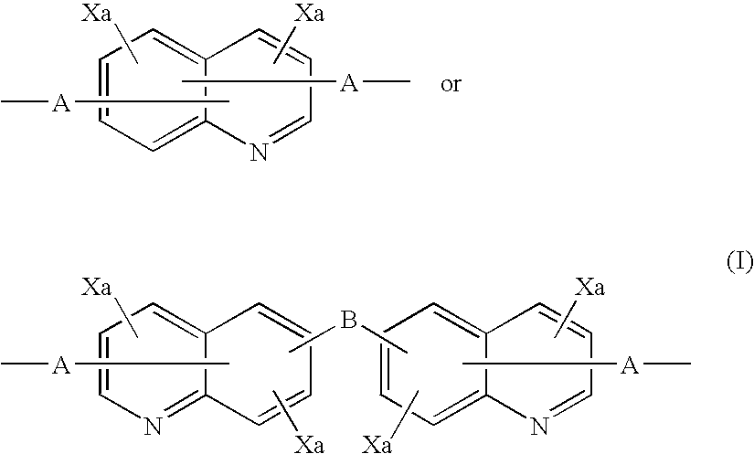
Image

Examples
example 1
Synthesis of Diboronic Acid Ester Quinoline Derivative
[0080] A Grignard reagent was prepared by gradually adding a THF solution of 6,6′-bis[2-(4-bromophenyl)-3,4-diphenylquinoline] (30 mmol) to a mixture of magnesium (1.9 g, 80 mmol) and THF under a flow of argon while stirring well. The Grignard reagent thus obtained was gradually added dropwise over 2 hours to a THF solution of trimethyl borate (300 mmol) at −78° C. while stirring well, and the mixture was then stirred at room temperature for 2 days. The reaction mixture was poured into 5% dilute sulfuric acid containing crushed ice and stirred. The aqueous solution thus obtained was extracted with toluene, and the extract was concentrated to give a colorless solid. The solid thus obtained was recrystallized from toluene / acetone (½) to give a diboronic acid quinoline derivative as colorless crystals (40%). The diboronic acid quinoline derivative (12 mmol) thus obtained and 1,2-ethanediol (30 mmol) were refluxed in toluene for 10 ...
example 2
Synthesis of Copolymer (1) of Quinoline Derivative and Branched Structure Derivative
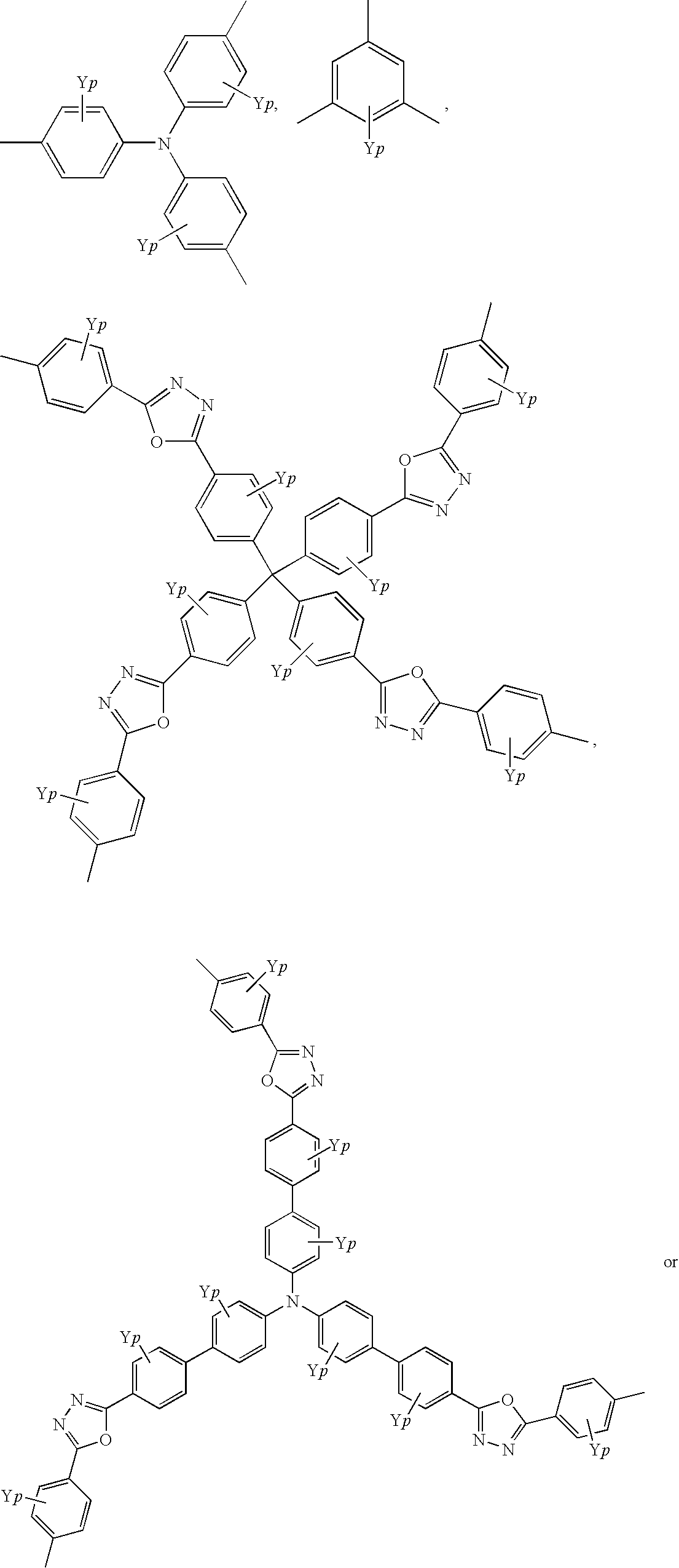
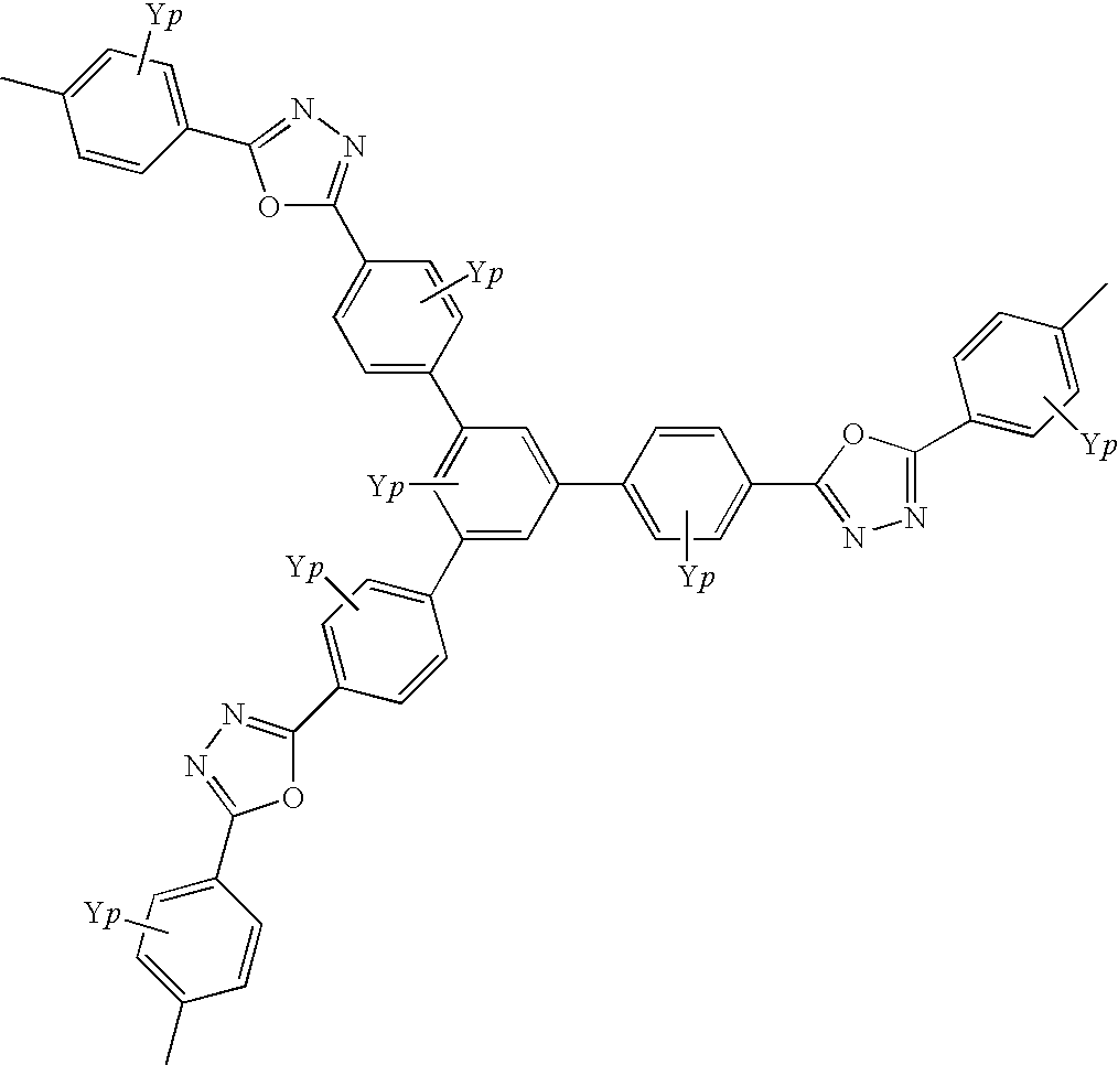
[0081] A 2 M aqueous solution of K2CO3 was added to a toluene solution of the tribromo branched structure monomer represented by the structural formula below (1 mmol), the dialkoxydibromobenzene compound represented by the structural formula below (9 mmol), the diboronic acid ester quinoline derivative synthesized in Example 1 (10 mmol), and Pd(0)(PPh3)4 (0.2 mmol) under a flow of argon, and the mixture was refluxed for 48 hours while stirring vigorously.
[0082] The reaction mixture was cooled to room temperature and then poured into a large amount of methanol so as to precipitate a solid. The solid thus precipitated was filtered by suction and washed with methanol to give a solid. The solid thus obtained by filtration was dissolved in toluene, and then poured into a large amount of acetone so as to precipitate a solid. The solid thus precipitated was filtered by suction, and washed with acetone to...
example 3
Synthesis of Copolymer (2) of Quinoline Derivative and Branched Structure Derivative
[0083] 6,6′-Bis[2-(4-fluorophenyl)-3,4-diphenylquinoline] (9 mmol), the branched structure monomer represented by the structural formula below (1 mmol), the dialkoxydihydroxybenzene compound represented by the structural formula below (9 mmol), potassium carbonate (15 mmol), anhydrous NMP (40 mL), and anhydrous toluene (20 mL) were heated and refluxed under a flow of nitrogen for 30 hours while stirring vigorously.
[0084] After adding NMP (60 mL) to the reaction mixture, it was cooled to room temperature. The solution thus obtained was poured into a large amount of distilled water to precipitate a solid. The solid thus precipitated was filtered by suction and washed with distilled water, methanol, and acetone to give a solid. The solid thus obtained by filtration was dissolved in toluene and then poured into a large amount of acetone to give a solid. The solid thus precipitated was filtered by suct...
PUM
| Property | Measurement | Unit |
|---|---|---|
| Stability | aaaaa | aaaaa |
Abstract
Description
Claims
Application Information