Cardiac valve annulus restraining device

a technology of annulus and valve, applied in the field of medical devices, can solve the problems of reducing the service life of the valve, and reducing the effect of regurgitation

Inactive Publication Date: 2007-02-01
MEDTRONIC VASCULAR INC
View PDF11 Cites 586 Cited by
  • Summary
  • Abstract
  • Description
  • Claims
  • Application Information

AI Technical Summary

Benefits of technology

[0011] Another aspect of the invention provides a device for treating mitral valve regurgitation. The device includes a flexible restraining member having a plurality of anchor members extending from the flexible restraining member and at least one adjustment member attached to the end portions of the flexible restraining member. When...

Problems solved by technology

Heart valves, such as the mitral, tricuspid, aortic and pulmonic valves, are sometimes damaged by disease or by aging, resulting in problems with the proper functioning of the valve.
Heart valve problems take one of two forms: stenosis, in which a valve does not open completely or the opening is too small, resulting in restricted blood flow; or insufficiency, in which blood leaks backward across a valve when it should be closed.
In common practice, repair or replacement requires open-heart surgery with its attendant risks, expense, and extended recovery time.
Open-heart surgery also requires cardiopulmonary bypass with risk of thrombosis, stroke, and infarction.
Any one or more of the mitral valve structures, i.e., the anterior or posterior leaflets, the chordae, the papillary muscles or the annulus may be compromised by damage from disease or injury, causing the mitral valve insufficiency.
In cases where there is mitral valve insufficiency, there is some degree of annular dilatation resulting in mitral valve regurgitation.
Thus, without correction, the mitral valve insufficiency may lead to disease progression and/or further enlargement and worsening of th...

Method used


Image

  • Cardiac valve annulus restraining device
  • Cardiac valve annulus restraining device
  • Cardiac valve annulus restraining device

Examples


Embodiment Construction

[0024] Throughout this specification, like numbers refer to like structures.

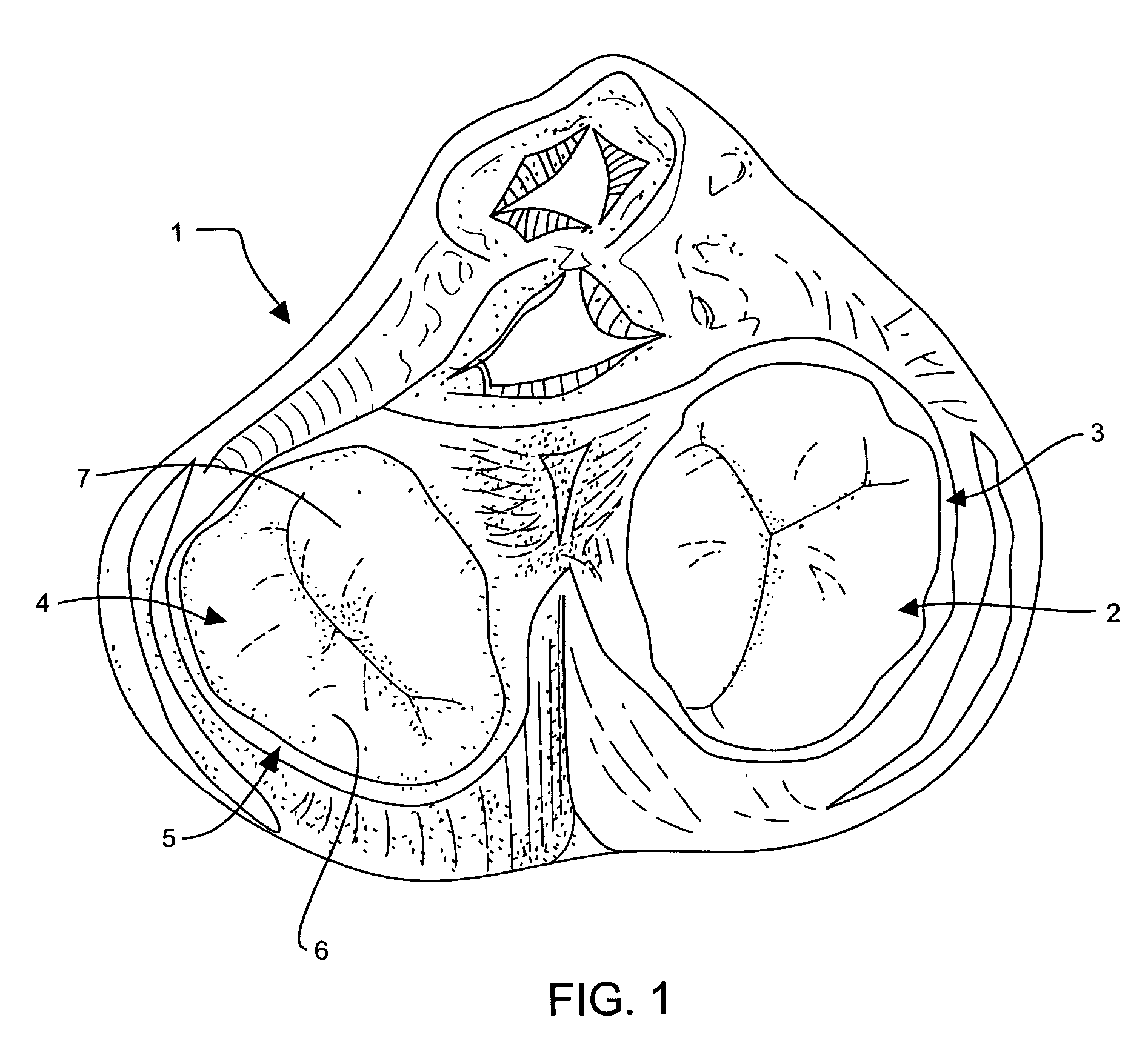
[0025] Referring to the drawings, FIG. 1 shows a cross-sectional view of heart 1 having tricuspid valve 2 and tricuspid valve annulus 3. Mitral valve 4 is adjacent mitral valve annulus 5. Mitral valve 4 is a bicuspid valve having anterior cusp 7 and posterior cusp 6. Anterior cusp 7 and posterior cusp 6 are often referred to, respectively, as the anterior and posterior leaflets.

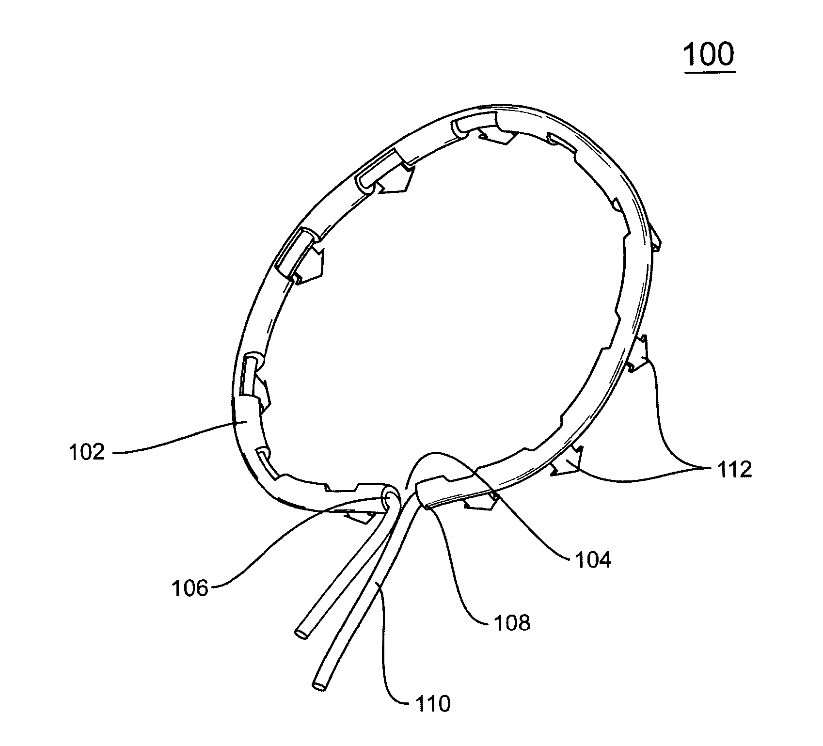
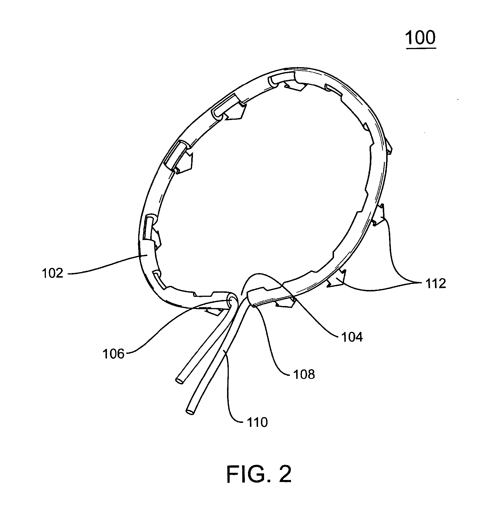
[0026]FIG. 2 portrays a flexible restraining device 100 for treating mitral valve regurgitation. Restraining device 100 includes a flexible member 102 that is depicted in the figure in an arcuate shape that the member will assume upon delivery to a location adjacent a mitral valve. Flexible member 102 is made of a flexible, biocompatible material that has “shape memory” so that flexible member 102 can be extended into an elongated configuration and inserted into a delivery catheter, but will assume a curved shape and dimensions when...


PUM


Abstract

A catheter based system for treating mitral valve regurgitation includes a restraining device having a flexible member, a plurality of movable anchor members attached to the outer surface of the flexible member, and an adjustment filament attached to the ends of the flexible member. One embodiment of the invention includes a method for attaching a flexible restraining device to the annulus of a mitral valve, and adjusting the length of the adjustment filament attached to the flexible member of the restraining device, thereby reshaping the mitral valve annulus so that the anterior and posterior leaflets of the mitral valve close during ventricular contraction.

Description

TECHNICAL FIELD [0001] This invention relates generally to medical devices for treating mitral valve regurgitation, and particularly to a cardiac valve annulus restraining system and method of using the same. BACKGROUND OF THE INVENTION [0002] Heart valves, such as the mitral, tricuspid, aortic and pulmonic valves, are sometimes damaged by disease or by aging, resulting in problems with the proper functioning of the valve. Heart valve problems take one of two forms: stenosis, in which a valve does not open completely or the opening is too small, resulting in restricted blood flow; or insufficiency, in which blood leaks backward across a valve when it should be closed. Valve replacement may be required in severe cases to restore cardiac function. In common practice, repair or replacement requires open-heart surgery with its attendant risks, expense, and extended recovery time. Open-heart surgery also requires cardiopulmonary bypass with risk of thrombosis, stroke, and infarction. [00...

Claims


Application Information

Patent Timeline
IPC IPC(8): A61F2/24
CPCA61F2/2445A61F2250/001A61F2/2466A61F2/2433
Inventor DOUK, NAREAK
Owner MEDTRONIC VASCULAR INC
Why Eureka
Try Eureka