Apparatus and method for purification of corrosive gas streams

a technology of corrosive gas and apparatus, which is applied in the direction of bromine, magnesium halides, separation processes, etc., can solve the problems of high corrosive to manufacturing system equipment, the moisture content of the ppm range of the deposited gas is too wet, and the most difficult impurities to remove from the gas are too w

Inactive Publication Date: 2007-02-08
MYKROLIS CORP +1
View PDF13 Cites 10 Cited by
  • Summary
  • Abstract
  • Description
  • Claims
  • Application Information

AI Technical Summary

Benefits of technology

[0017] The zirconia may be in the form of a porous solid body, in the form of a plurality of granular particles, in the form of a high surface area solid material, or deposited within the pores of a porous solid material. Purification of the gas stream occurs as the gas stream is passed through or over zirconia or solid material that comprises zirconia.
[0018] In another embodiment, the present invention is an apparatus for purifying a stream of corrosive gas. The apparatus comprises a container comprising a gas-tight chamber therein and zirconia, disposed within the gas-tight chamber. The container further comprises a gas inlet port and a gas outlet port penetrating the container and providing fluid communication for flow of the corrosive gas into the chamber from the exterior of the container and out of the chamber to the exterior of the container. In the embodiments where the impurity being removed is water, zirconia is provided in a quantity sufficient to reduce the water content of the stream of corrosive gas to not more than about 100 ppb as the corrosive gas passes through the chamber where it contacts zirconia. During the operation of this device, the zirconia within the chamber remains substantially unaffected by the corrosive gas. The container itself can be made of a halogen-resistant metal or can be described to have a halogen-resistant lining, so that the housing itself is not susceptible to corrosion and thus does not become the limiting factor in the service life of the system.

Problems solved by technology

Water is one of the most common and yet most difficult impurities to remove from gases, if unwanted.
In the manufacture of many electronic products, such as high purity wafers, chips, integrated circuits or ceramics, however, moisture contents of depositing gases in the ppm range are too wet.
Further, there are a number of gases used in the manufacture of high purity products which in the presence of water become highly corrosive to manufacturing system equipment.
Corrosion in turn causes gas leaks and component failures in valves, regulators, filters, flow controllers, tubing and fittings.
The corrosive effect of the halogen gases in the presence of water not only causes damage to the equipment, it also is detrimental to the products being made therefrom.
The water content itself causes problems in product integrity and yield.
In addition, the gas-induced corrosion of the equipment, tubing, etc., generates small particles of corroded materials.
These become entrained in the gas stream and are carried into the product formation chambers, where they deposit onto products being formed, thus ruining the products and decreasing yield.
Current technologies are not compatible with liquid phase corrosives.
Attempts to use silica, alumina, titanium tetrachloride, and other oxides, halides, etc. to remove moisture from corrosive gases, e.g. halogen-containing gases, have not been successful.
Regulators, which are typically placed directly downstream of the source to control the pressure in the system, are particularly susceptible to wet corrosive gases, because the high pressure differential leads to Joule-Thompson condensation of moisture.
Condensed moisture is extremely detrimental in an ultra high purity corrosive gas delivery system.
However, purification devices immediately downstream of the corrosive gas source are susceptible to high pressures and high flow rates that are often in the liquid regime of the phase diagram.
Furthermore, certain corrosive gases with relatively low vapor pressure, e.g., HBr, Br2, and SiCl4, often liquefy in the purification device.
Most purification technologies currently available for use with corrosive gases do not satisfy the requirements necessary to be placed immediately downstream of the source and are incompatible with liquid phases.
The devices that are available for use under these conditions do not maintain their performance over a long period of time.
Such materials work well initially, but are susceptible to degradation over time (approximately 6 months to a year).
However, such materials are not highly versatile and may only be used with a selection of halide gases.
These dehydration agents are also susceptible to degradation over time and can release volatile byproducts when they decompose.
Additionally, the dehydration agents cannot be regenerated, which is an important process that reduces environmental waste and increases process efficiency.
Consequently, the problem of removal of moisture down to 100 ppb from corrosive chlorine-containing gases remains a significant problem in many fields.
Those processes which are being used are expensive often because of the very short service life of the dehydrating materials and the need for their frequent replacement.
In addition, since it is difficult to determine the exact rate of deterioration of the dehydrating materials in the presence of the corrosive halogen and halide gases, users of such dehydrating materials must schedule their discard and replacement at intervals less than the shortest expected service life.

Method used


Image

  • Apparatus and method for purification of corrosive gas streams
  • Apparatus and method for purification of corrosive gas streams

Examples


example 1

Preparation of Zirconia for Use in the Present Invention

[0052] A preferred method for preparation of zirconia for use in the instant invention comprises:

[0053] 1. Mixing Mg(OCOCH3)2 with ZrO2 in water and allowing the insoluble magnesium impregnated zirconia to collect on a surface. ZrO contained about 1.5 wt. % hafnium and has a single point surface area of about 35 m2 / g.

[0054] 2. The magnesium-zirconium-water mixture is filtered, optionally pellitized, and the insoluble material is dried about 16-24 hours at about 150° C.

[0055] 3. The material is then subjected to heating at about 300° C. for about 15 hours.

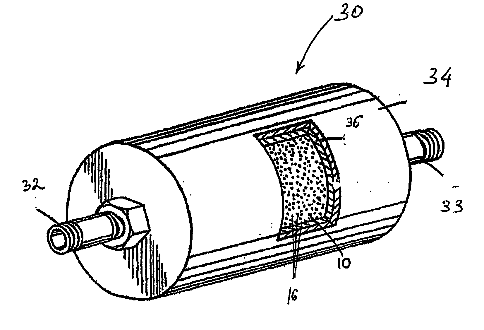
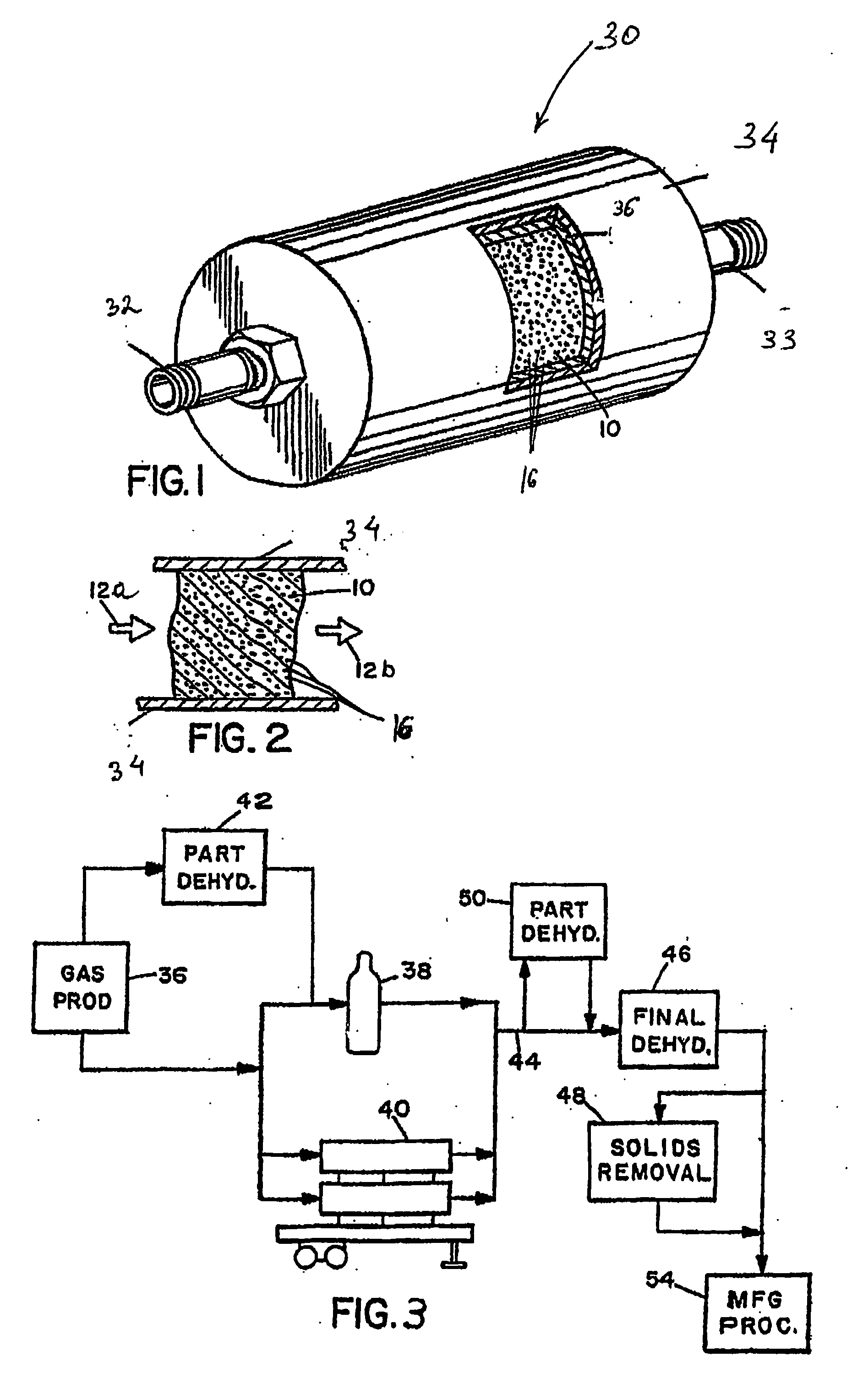
[0056] 4. The material is then put into canisters or other end use devices.

[0057] 5. The material is activated at about 200-500° C., preferably in 95% Ar / 5% H2, until the amount of moisture released drops to an acceptable level. This requires, typically, 1.5 to 4 hours. The end use device is shipped to the end user.

[0058] 6. The device is conditioned with halide gas unti...


PUM

PropertyMeasurementUnit
temperatureaaaaaaaaaa

Abstract

A process, composition and apparatus for the removal of impurities from corrosive gases, particularly halogen-containing gases, down to about 100 ppb concentration are described. The critical component is zirconia (ZrO2), which in a variety of physical forms is capable of dehydrating such gases. The zirconia can be in the form of a coating on a substrate, as a granular bulk material, or deposited within the pores of a porous body. The zirconia is retained in a simple container which is easily installed in a gas supply line, such as to a gas- or vapor-deposition manufacturing unit. The purification process can be operated for long periods of time in the presence of these gases. The invention provides final purification to gas streams intended for gas- or vapor-deposition formation of high purity electronic, prosthetic or similar products, and can be used in combination with a preliminary dehydration process or a solid particulate removal unit upstream.

Description

RELATED APPLICATIONS [0001] This application claims the benefit of U.S. Provisional Application No. 60 / 480,709, filed on Jun. 23, 2003. The entire teachings of the above application are incorporated herein by reference.BACKGROUND OF THE INVENTION [0002] Water is one of the most common and yet most difficult impurities to remove from gases, if unwanted. Water is of course ubiquitous in almost all ambient environments. Even systems which are nominally referred to as “dry” usually have significant amounts of water, and most drying processes can reduce the moisture content of a gas only to a “minimum” which is still in the parts per million (ppm) range. However, since for many purposes water contents in the ppm range are quite acceptable, there are numerous patents and articles in the literature dealing with such types of “ppm drying processes.”[0003] In the manufacture of many electronic products, such as high purity wafers, chips, integrated circuits or ceramics, however, moisture con...

Claims


Application Information

Patent Timeline
Patent Type & Authority Applications(United States)
IPC IPC(8): C01F11/22C01F5/28B01D53/26B01D53/28
CPCB01D53/261B01J20/3483B01J20/0211B01J20/041B01J20/06B01J20/28057B01J20/28097B01J20/3236C01B7/0718C01B7/0743C01B7/093C01B7/096C01B7/197C01B7/20C01B7/24B01J20/3204B01J20/3433B01J20/3458B01D53/28B01D53/26
Inventor ALVAREZ, DANIEL JR.LEV, DANIEL A.SPIEGELMAN, JEFFREY J.NGUYEN, TRAM D.HOLMES, RUSSELL J.
Owner MYKROLIS CORP
Why Eureka
Try Eureka