
High performance cooling assembly for electronics

a cooling assembly and high-performance technology, applied in the field of electronic circuit board cooling systems, can solve the problems of low density of air, poor thermal conductivity compared to other materials, and difficult cooling of certain configurations of electronic circuits, and achieve the effect of high performan

Inactive Publication Date: 2007-02-15
HALL JACK PHILLIP
View PDF29 Cites 103 Cited by
  • Summary
  • Abstract
  • Description
  • Claims
  • Application Information

AI Technical Summary

Benefits of technology

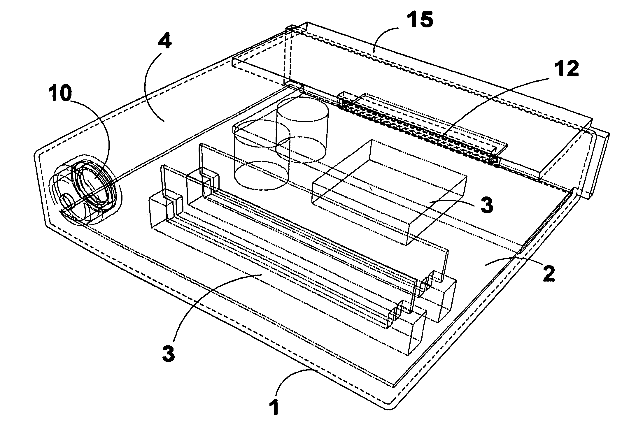
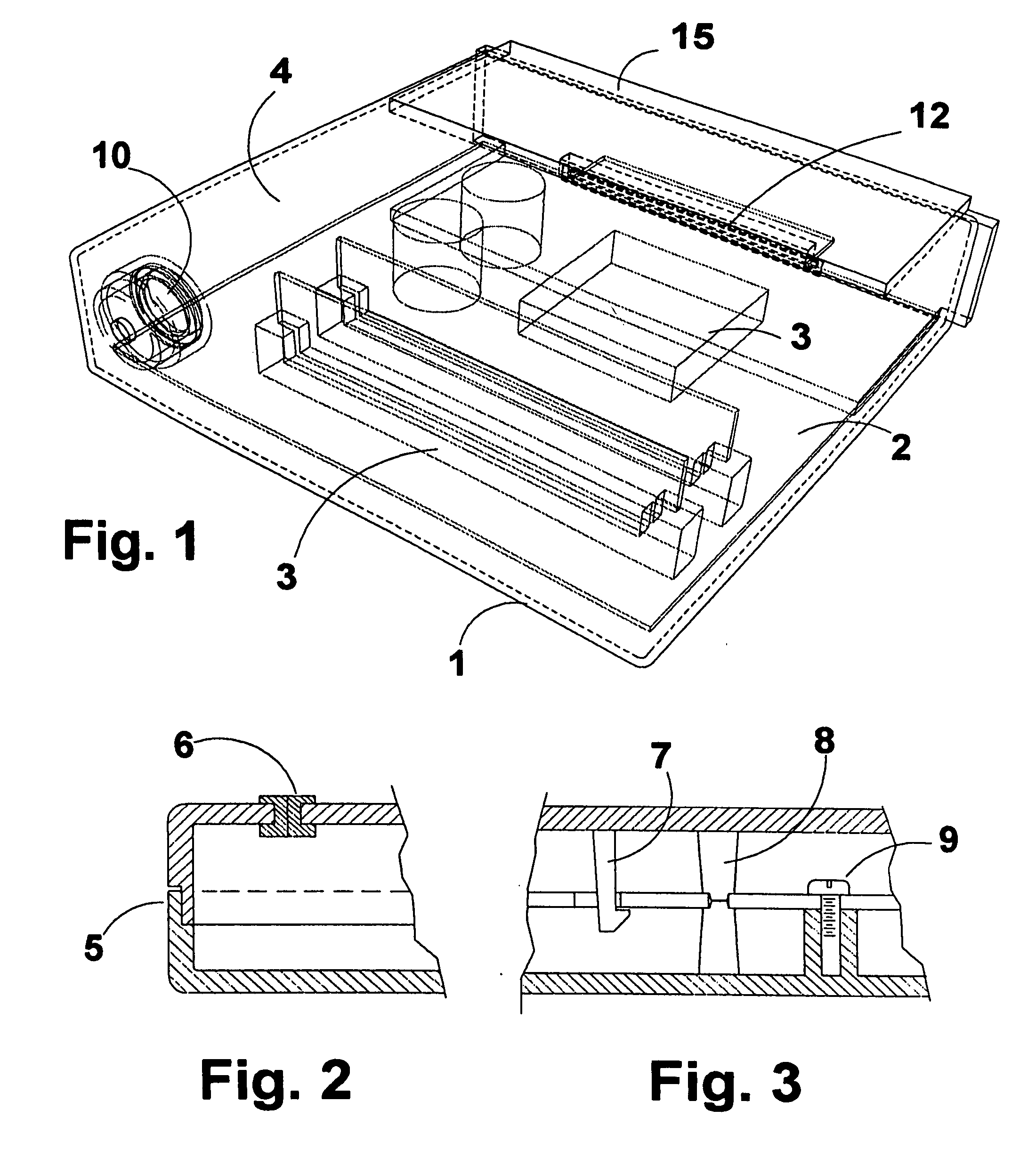
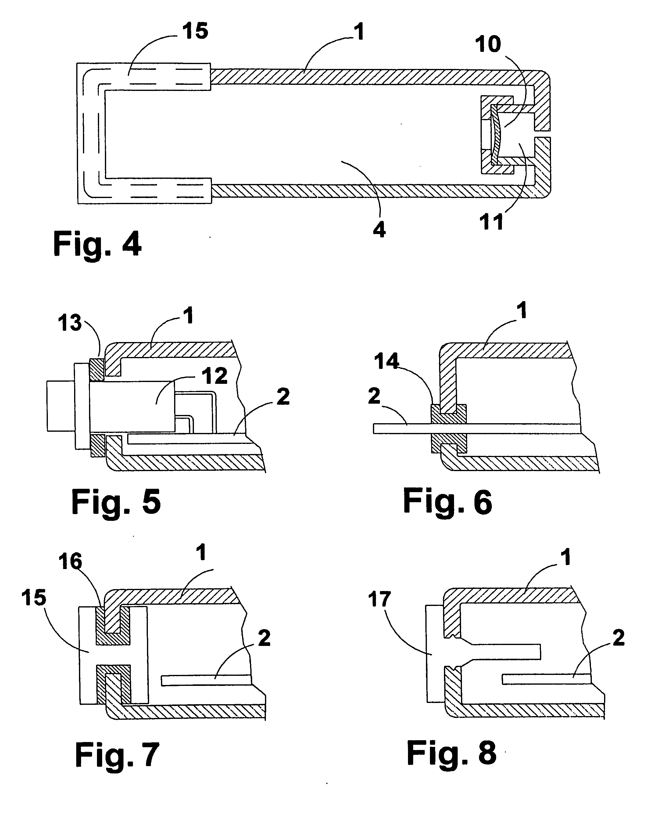
[0016] The present invention provides a high performance method for the cooling of complex, heat generating circuit boards and other complex electronic assemblies, using a dielectric liquid as a heat conducting medium, without necessitating the use of complex apparatus for circulating cooling liquid. This is accomplished using a container enclosing the entire electronic assembly such that the assembly is submerged in the dielectric liquid. A thermally conductive plate is in contact with the fluid and the plate extends beyond the exterior wall of the container. The plate can be attached to a thermal pathway such as a heat pipe that is connected to a heat exchanger. By cooling the heat pipe and consequently cooling the conductive plate, the fluid inside the container becomes cooler through diffusion, and consequently the electronic components are cooled. Electrical connection between the electronic assembly within the container and other external electronic devices is made through a sealed electrical connector. The protruding connector may be attached to a mating connector on either a printed wiring board or electrical wiring cable.
[0019] b) The sealed liquid filled containers are easy to remove and replace, without risk of spillage.
[0023] f) The dielectric fluid used as a thermal transfer medium is sealed within the enclosure and does not circulate outside of the enclosure. The absence of fluid couplings, tubing, valves and pumps makes this invention more reliable, mitigating the issues of spillage and leakage.
[0024] g) The absence of fluid couplings, tubing, valves and pumps makes this invention more economical than fluid circulating inventions due to the reduced number of parts.
[0026] i) When compared to conventional fan cooling, this invention has a lower noise potential.

Problems solved by technology

Fans are widely used to provide cooling in electronics enclosures, but certain configurations of electronic circuits are difficult to cool sufficiently solely with forced air.
Air has low density and poor thermal conductivity compared to other materials.
Moving high volumes of air typically generates high levels of noise and turbulence.
On the other hand, use of liquid with electronic assemblies is problematic because of the potential for spillage and leakage.
While this solution may work for microprocessors and other flat components; it is impractical where heat generating components of odd shapes and / or a large number of components are present.
Further, the system is prone to leaks due to the numerous fluid connections.
The heat flow path is limited to the specific components that are in contact with the pads, and the system is prone to leaks due to the numerous fluid fittings.
Because of the numerous fluid couplings, this design is prone to leakage.
The plate is not conformal; it does not engulf each electronic device as a fluid does, and so heat transfer is limited.
Only the component surface in contact with the substrate is cooled and therefore heat transfer is limited.
This invention can accommodate slight variations in device planarity but is impractical for electronic assemblies containing a wide range of component shapes and circuit board configurations.
The invention is an improvement over the epoxy encapsulation method typically used to package semiconductor devices, however, it is not suitable for larger assemblies of components such as a circuit board.
Systems that use a pumping device to circulate cooling liquid are difficult to seal because of the numerous connections between hoses, fittings, gaskets and pumps.

Method used


Image

  • High performance cooling assembly for electronics
  • High performance cooling assembly for electronics
  • High performance cooling assembly for electronics

Examples


Embodiment Construction

[0070] The present invention provides advantageous devices and methods for cooling complex and often rather large, electronics assemblies. In many cases, the electronic assemblies are or include circuit boards. As explained herein, the devices utilize thermally conductive, dielectric liquid-filled containers in which circuit boards or other complex electronic devices are mounted. The heat generated by components on the circuit board or other complex device is conducted through the liquid and through a thermally conductive plate that extends from the interior of the container in contact with the liquid to the exterior of the container, thereby providing an efficient heat conduction pathway. From the exterior surface of the plate, the heat can be conducted or dissipated away from the container.

[0071] Additional advantageous features of such devices relate to compensating for thermal expansion of the large volume of liquid in the container, the mechanisms used to thermally couple the ...


PUM


Abstract

An assembly for high performance cooling of electronics is described that includes a container for heat transfer liquid in which complex electronic assemblies are immersed. The electronics are sealed inside the liquid container such that an electrical connector protrudes to the exterior of the container. A thermally conductive plate is made part of the liquid filled container assembly such that a portion of the plate is in contact with the liquid and a portion of the plate protrudes from or forms part of the exterior of the container.

Description

RELATED APPLICATIONS [0001] This application claims the benefit of U.S. Provisional Application No. 60 / 688,641 filed on Jun. 9, 2005, which is incorporated herein by reference in its entirety.FIELD OF THE INVENTION [0002] The present invention relates to the field of cooling systems for electronic circuit boards. BACKGROUND OF THE INVENTION [0003] The following discussion is provided solely to assist the understanding of the reader, and does not constitute an admission that any of the information discussed or references cited constitute prior art to the present invention. [0004] Heat dissipation is an important operational aspect of electronic assemblies. As performance and density of electronics increases, the devices typically produce more heat. Fans are widely used to provide cooling in electronics enclosures, but certain configurations of electronic circuits are difficult to cool sufficiently solely with forced air. Air has low density and poor thermal conductivity compared to o...

Claims


Application Information

Patent Timeline
IPC IPC(8): F28D15/00
CPCG06F1/183H05K7/20763G06F2200/201G06F1/20H05K7/20418
Inventor HALL, JACK PHILLIP
Owner HALL JACK PHILLIP
Learn More