
Electrode for electrolysis and method of manufacturing electrode for electrolysis

a manufacturing method and electrolysis technology, applied in the direction of electrolysis components, coatings, chemistry apparatus and processes, etc., can solve the problems of low ozone generating efficiency of ozone generating electrodes, easy complex devices, and difficult to generate ozone water having a desired concentration with a high efficiency, etc., to achieve the effect of efficient generation

Inactive Publication Date: 2007-02-15
SANYO ELECTRIC CO LTD
View PDF3 Cites 13 Cited by
  • Summary
  • Abstract
  • Description
  • Claims
  • Application Information

AI Technical Summary

Benefits of technology

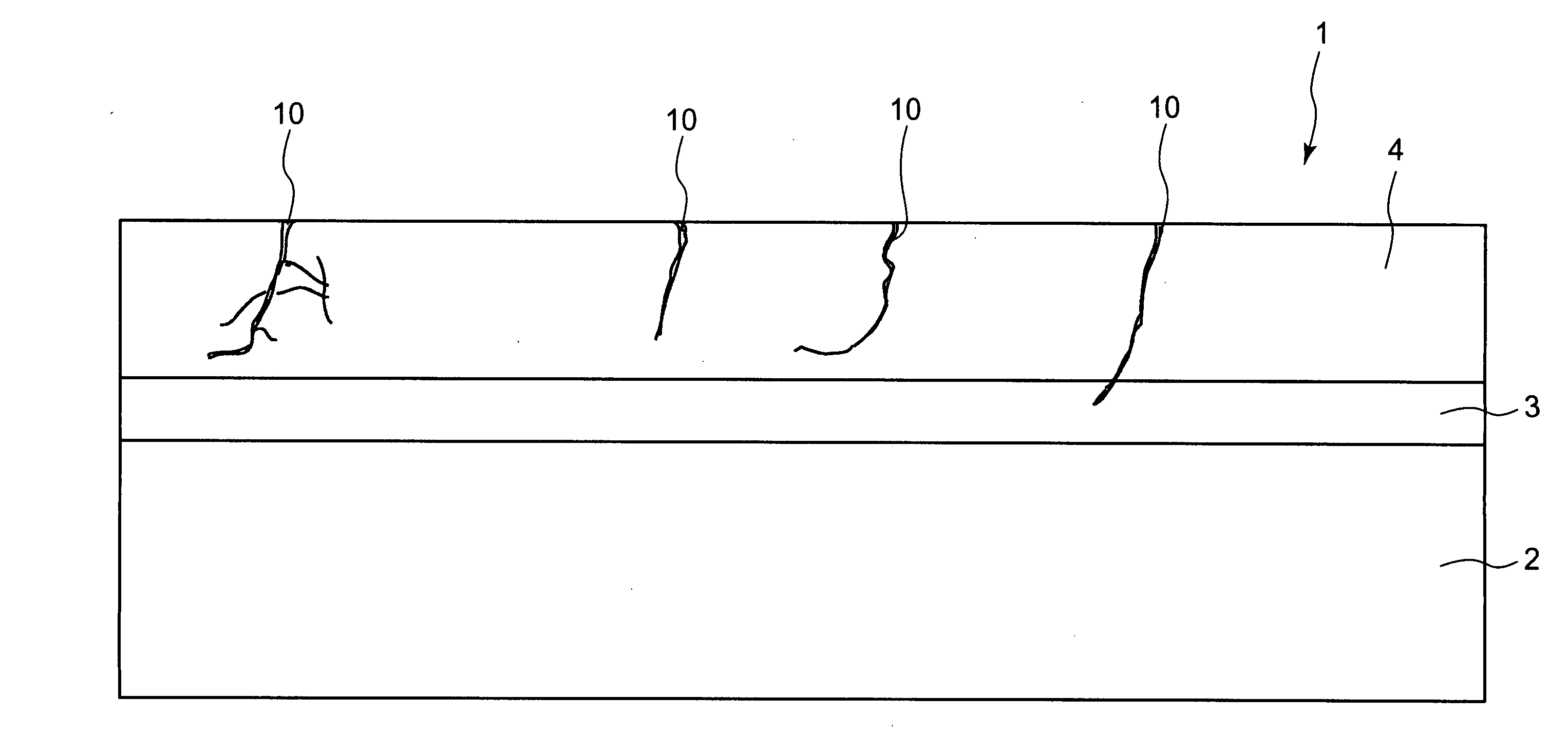
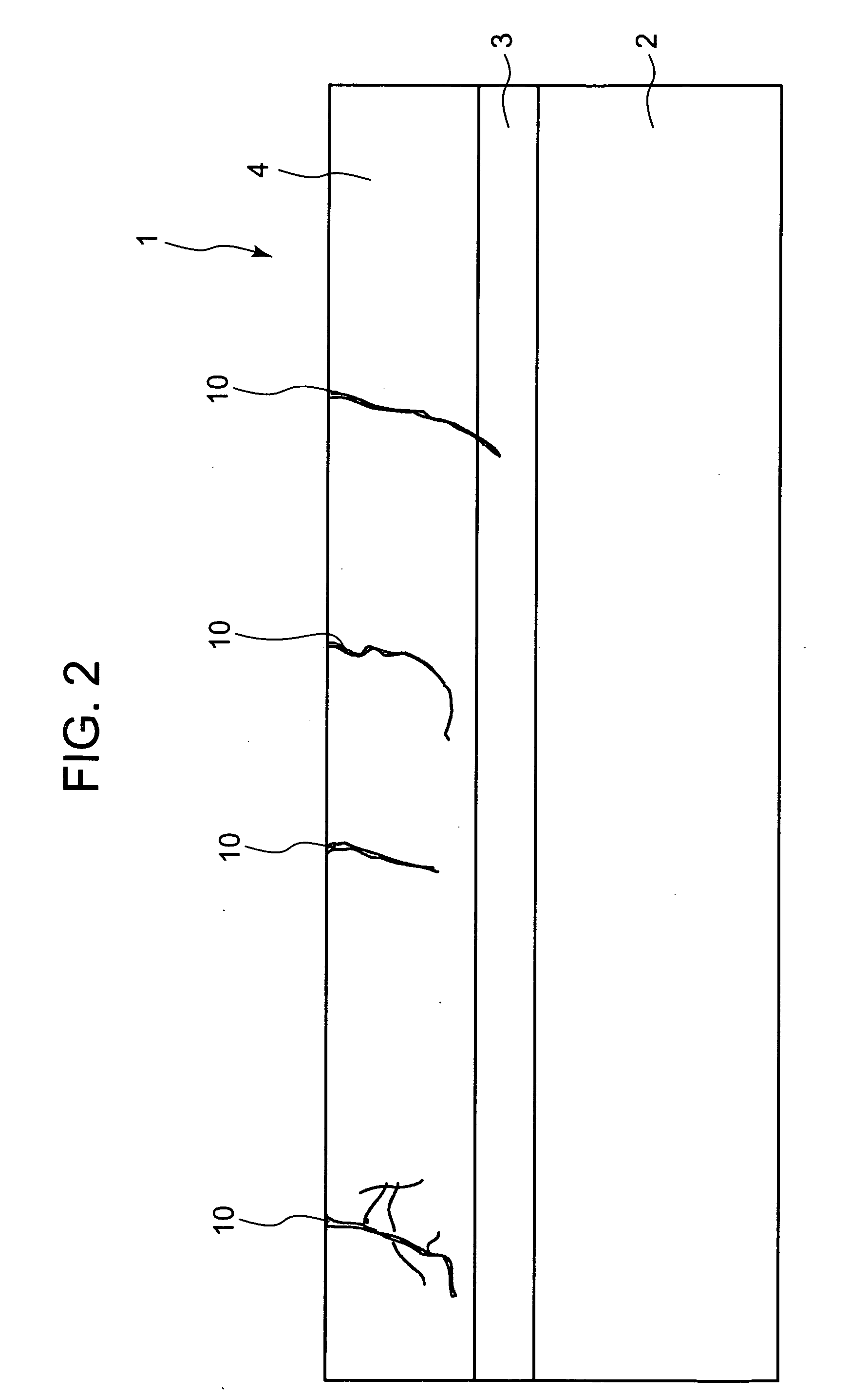
[0019] According to the first aspect of the present invention, the electrode for electrolysis comprises the substrate, and the surface layer formed on the surface of the substrate and including the dielectric material, the surface layer includes holes which continuously extend from the surface of the surface layer into the inside of the surface layer, and a distance from the hole closest to the surface of the substrate to the surface of the substrate is more than 0 and 2000 nm or less. The electrode for electrolysis can perform the electrolysis to efficiently generate ozone at a low current density.
[0030] When the cracks complicatedly repeat branching and combining, it is possible to form the cracks in which the distance from the hole closest to the intermediate layer to the intermediate layer is more than 0 and 2000 nm or less. Therefore, since the distance from the hole to the surface of the substrate is more than 0 and 2000 nm or less, in a case where the electrolysis is performed by the resultant electrode, the electrons can move in the electrode via the impurity level in the surface layer positioned from the holes to the substrate surface or owing to the Fowler-Nordheim tunnel. Accordingly, in the electrode reaction in the anode, the empty level in the vicinity of the bottom of the conduction band has the energy level which is higher than the Fermi level as much as about the half of the band gap, can receive the electrons from the electrolyte, and excites the movement of the electrons at the higher energy level. Accordingly, ozone can efficiently be generated at the lower current density.

Problems solved by technology

However, in the above-described ozone water generating method in which the ozone gas is generated by the ultraviolet lamp or the electric discharge system as described above to dissolve this ozone gas in water, there is required the ozone gas generating device or an operation for dissolving the ozone gas in water, and the device easily becomes complicated.
In this method, since the generated ozone gas is dissolved in water, there is a problem that it is difficult to generate ozone water having a desired concentration with a high efficiency.
However, the element has a low ozone generating efficiency for the ozone generating electrode, and it is difficult to generate ozone water by a high-efficiency electrolysis method.
When ozone water is generated by the electrolysis method using such a conventional ozone generating electrode, electrolysis at a high current density is required for generating ozone, and there is a problem in energy consumption or electrode life.

Method used


Image

  • Electrode for electrolysis and method of manufacturing electrode for electrolysis
  • Electrode for electrolysis and method of manufacturing electrode for electrolysis
  • Electrode for electrolysis and method of manufacturing electrode for electrolysis

Examples


embodiment 1

[0047] Next, there will be described a method of manufacturing an electrode for electrolysis with reference to a flow chart of FIG. 4. In this manufacturing method, the surface of a conductive substrate 2 is coated with an intermediate layer 3, and the surface of this intermediate layer 3 is coated with a surface layer 4.

[0048] First, a titanium plate having a thickness of 1 mm, a length of 80 mm and a width of 20 mm is used as the conductive substrate 2, and the surface (surface having a length of 80 mm and a width of 20 mm) of this conductive substrate 2 is polished by a sandpaper (step S1). It is to be noted that in an ozone generating electrode 1 of the present embodiment, the surface of the conductive substrate 2 is coated with the intermediate layer 3 and the surface layer 4 on only one side, and this surface layer 4 is opposed to a counter electrode, and used as a reactive surface of electrolysis. In a case where the ozone generating electrode 1 of the present invention is u...

embodiment 2

[0089] Next, another embodiment of the present invention will be described. An ozone generating electrode 1 of the present embodiment is different from that of Embodiment 1 in that instead of tantalum oxide in the surface layer 4 of Embodiment 1, aluminum oxide, titanium oxide or tungsten oxide is used.

[0090] It is to be noted that in Embodiment 1, to form the surface layer 4 of tantalum oxide, to the solvent prepared so that the mixture ratio between n-butyl acetate and dimethyl formamide is 95:5, tantalum ethoxide is dissolved in such an amount as to obtain the tantalum concentration of 1.45 mol / l, thereby forming the surface layer constituting material. On the other hand, in the present embodiment, in a case where a surface layer 4 is made of aluminum oxide, isoamyl acetate is used as a solvent, and in this solvent, an organic metal including aluminum (Al) is dissolved to obtain a surface constituting material. In a case where the surface layer 4 is made of titanium oxide, n-but...


PUM

PropertyMeasurementUnit
Distanceaaaaaaaaaa
Distanceaaaaaaaaaa
Nanoscale particle sizeaaaaaaaaaa

Abstract

An object is to provide an electrode for electrolysis capable of generating ozone water with a high efficiency by electrolysis of water at a low current density. An ozone generating electrode includes: a substrate; and a surface layer formed on the surface of the substrate and including a dielectric material, the surface layer includes holes which inwardly continuously extend from the surface of the surface layer, and a distance from the hole closest to the surface of the substrate to the surface of the substrate is more than 0 and 2000 nm or less.

Description

BACKGROUND OF THE INVENTION [0001] 1. Field of the Invention [0002] The present invention relates to an electrode for electrolysis for use in an industrial or household electrolysis process, and a method of manufacturing the electrode for electrolysis. [0003] 2. Description of the Related Art [0004] In general, ozone is a substance having a very strong oxidizing power. There is expected broad utilization of water in which ozone has been dissolved, so-called ozone water in a cleaning and sterilizing treatment, such as application of ozone water to water supply and sewage systems or foods or application of ozone water to a cleaning treatment in a semiconductor device manufacturing process or the like. As a method of generating ozone water, there are known: a method of dissolving, in water, ozone generated by ultraviolet irradiation or electric discharge; a method of generating ozone in water by electrolysis of water and the like. [0005] In Japanese Patent Application Laid-Open No. 11-...

Claims


Application Information

Patent Timeline
IPC IPC(8): C25C7/02C25B11/03B05D3/02B05D1/36
CPCC02F1/46109C02F1/4672C25B11/0405C25B1/13C25B11/03C02F2001/46142C25B11/051
Inventor IKEMATSU, MINEOKANEDA, KAZUHIRO
Owner SANYO ELECTRIC CO LTD
Learn More