Device for deionizing saline solutions

a technology of saline solution and device, which is applied in the direction of electrolysis components, filtration separation, lighting and heating apparatus, etc., can solve the problems of osmotic pressure, not directly usable, and more than 97% of the total water stock of oceans and seas salt water, etc., to overcome the problem of osmotic pressur

Inactive Publication Date: 2007-02-15
R CUBE PROJET
View PDF2 Cites 14 Cited by
  • Summary
  • Abstract
  • Description
  • Claims
  • Application Information

AI Technical Summary

Benefits of technology

[0034] The deionizing device according to the invention avoids all problems of electrode corrosion and clogging of the membranes and allows continuous operation of the device, without the need for periodic intervention. The whole of the installation functions simply and it is particularly effective for multiple applications such as the production of freshwater from seawater, the softening of hard water, the treatment of wastewater, the recuperation of toxic or precious metal ions and the production of ultra-pure water for industry.
[0052] a cell having an external wall totally impermeable to fluid, electrically insulating and non-ferromagnetic, deionizing chambers alternating with concentrating chambers compartmentalized by selectively ion-permeable membranes and likewise alternated, separated by dividers defining the chambers, and an external induction generator rotating within the plane of the membranes, acting on the whole length of the cell by producing a force on the ions of the ionized fluid circulating, at velocity, so that the cations pass through the cation-permeable membranes and the anions pass through the anion-permeable membranes, thereby developing a Hall effect potential on the internal wall of the end chambers of the cell,
[0061] the deionized fluid recovered at the exit the deionization conduit is treated with reverse osmosis, but at low pressures, in order to eliminate those non-ionic substances that may equally be present in the ionized fluid used and to provide an ultra-pure fluid.
[0066] According to another advantageous characteristic, upon exiting the deionizing cell, the electrodes are placed in contact with the base and acid solutions thereby allowing the recovery on the one hand of the electric energy produced by the electrochemical potential difference of the solutions and on the other hand of the products resulting from the electrolysis induced by the electrochemical reactions at the electrodes.
[0067] It is interesting to augment the efficiency of the device by means of a deionizing cell of spiral helicoidal shape, placing the cationic and the anionic chambers in proximity to one another and linking tern by means of an electrically conductive junction.

Problems solved by technology

The salt water of oceans and seas, representing more than 97% of the total water stock, is not directly usable and numerous industrial developments are undertaken to desalinate seawater, brackish water and waste waters before they are flushed into the drains.
Some advances in the use of solar thermal energy deserve consideration but remain currently very marginal.
Using less energy than thermal centers, these filtration techniques are increasingly competing with them.
The major physical problem of membrane techniques is that of osmotic pressure, which must be overcome in order to carry out the filtration.
The creation of these high pressures is energy-consuming and poses serious problems of membrane resistance at such a pressure gradient.
Since the salinity of seawater is higher than 20,000 ppm, electrodialysis is not applicable without high maintenance due to the corrosion of the electrodes and the blocking of membranes where electrochemical reactions take place under high electrical currents.
These surface charges constitute a diffusion barrier, reducing the bleed currents (selective diffusion of ions in the membrane), and are responsible for the precipitation of certain salts, thus clogging the membranes.
The problem then becomes one of suppressing the Hall effect, that is, of the electric field generated by the separation of the charges subjected to the Laplace force in order for the separation to take place.
By eliminating thus the principal datum of the problem, the American patent offers no solution to it.

Method used


Image

  • Device for deionizing saline solutions
  • Device for deionizing saline solutions
  • Device for deionizing saline solutions

Examples


Embodiment Construction

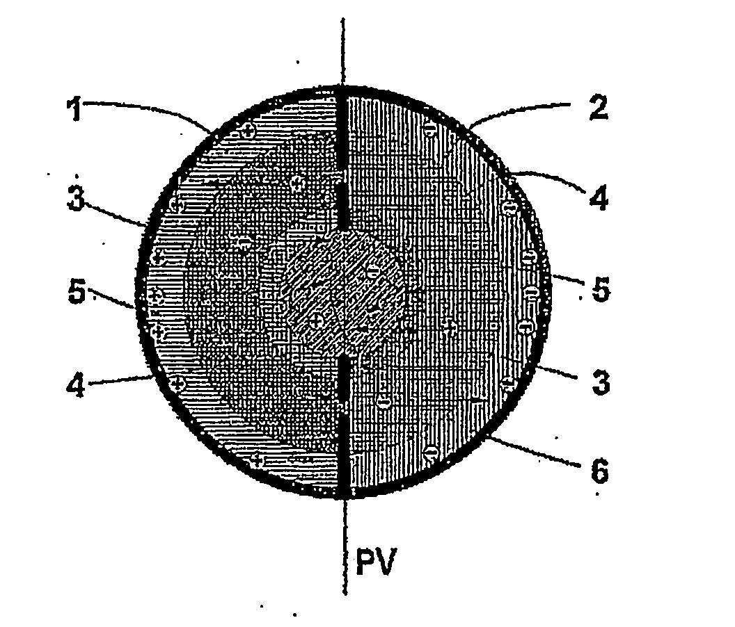
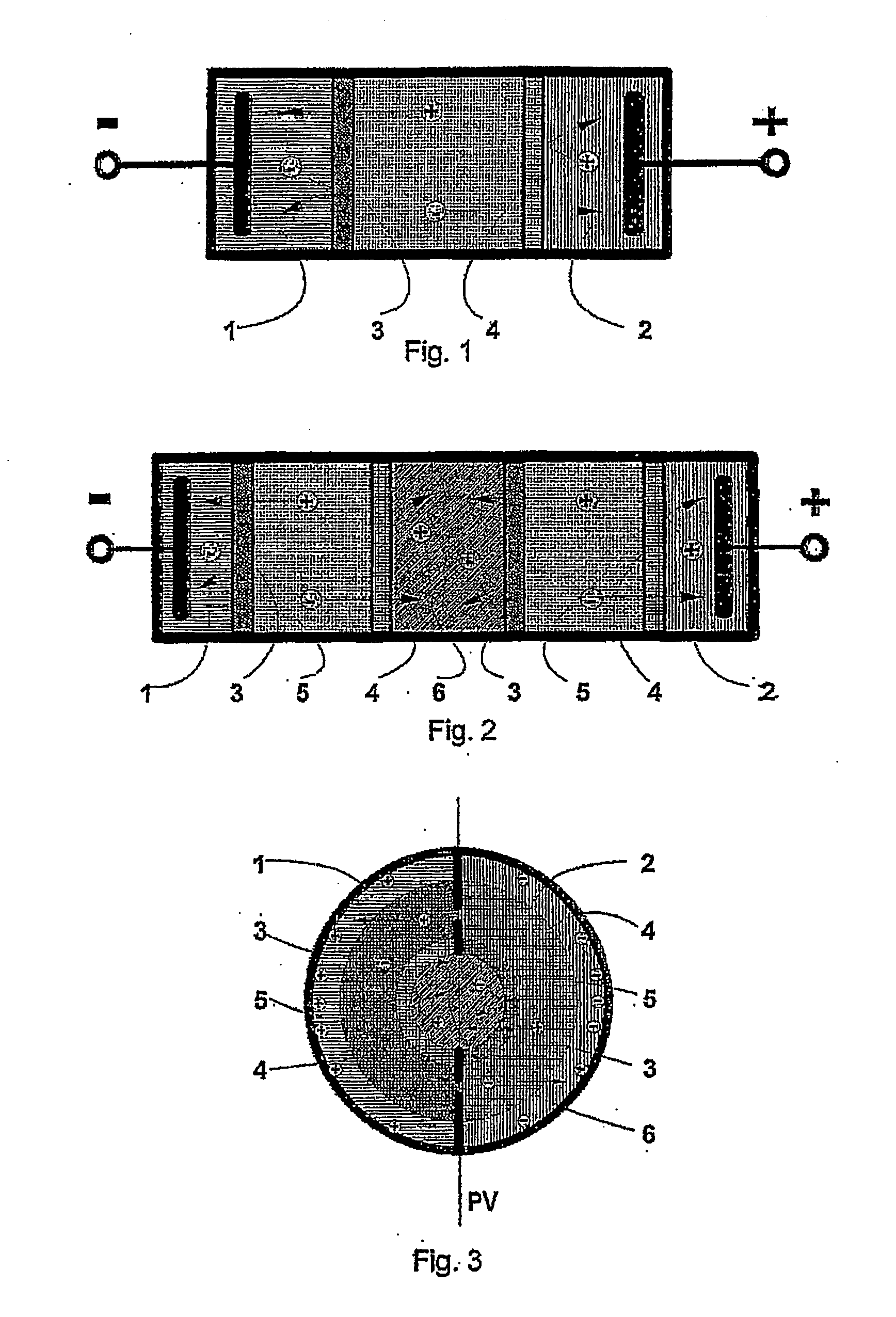
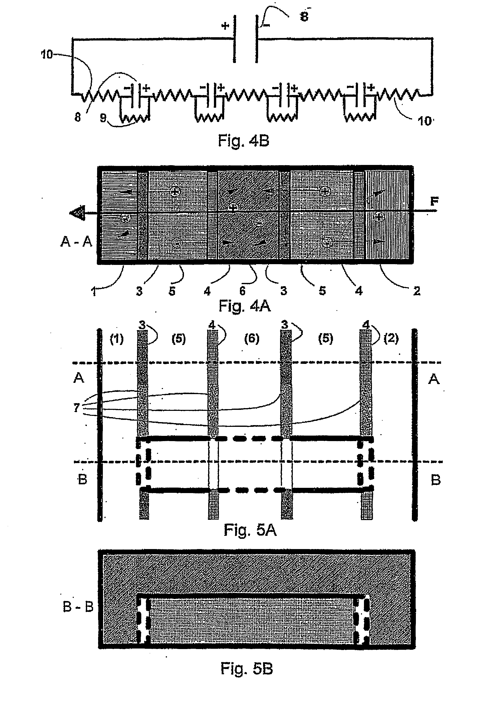
[0030] To this effect, the invention concerns a deionization device for saline solutions of a type defined below characterised in that it contains at least one deionization cell constituting a continuous conduit whose exterior wall is totally impermeable to fluid, electrically insulating and non-ferromagnetic, each cell comprising: [0031] a first element provided with an alternate pile of membranes, which are selectively ion-permeable, separated by dividers defining concentrating chambers, deionizing chambers, and a chamber at each end of the pile, [0032] a second element comprising a pile having a number of membranes equal to the first element but electrically insulating and separated by dividers extending the deionizing chambers, the concentrating chambers and the end chambers of the first element, [0033] the third element provided with only two chambers, one of them combining all concentrating chambers and end chambers, the other combining all deionizing chambers.

[0034] The deio...


PUM

PropertyMeasurementUnit
chargeaaaaaaaaaa
tangential velocityaaaaaaaaaa
electric fieldaaaaaaaaaa

Abstract

The invention relates to a device comprising a Laplace power generator acting on a deionizing cell provided with at least one deionizing cell comprising a first element provided with an alternate pile of membranes which are selectively ion-permeable and define concentrating chambers, deionizing chambers and a chamber on each end of the pile, a second element comprising a pile having a number of membranes equal to the first element but said membranes are electrically insulated and extend the chambers of the first element, and a third element provided with two chambers, one of them combining all concentrating chambers and end chambers, the other combining all deionizing chambers.

Description

FIELD OF THE INVENTION [0001] The invention concerns one or more deionization device(s) traversed by an ionized solution comprising a cell with: [0002] an envelope and [0003] a deionization chamber and a concentration chamber, separated by ion-permeable membranes, the ionized solution circulating along the membranes and the at least partially deionized solvent, being collected on leaving the deionization chamber. [0004] Water, although in inexhaustible supply on the planet since it undergoes a cycle of transformation, which is continually regenerating it, nevertheless becomes a precious element since its availability on land is highly variable and only pure fresh water, representing less than 2.5% of the total quantity of water in existence, is directly usable for consumption, agriculture and industry. [0005] The problem of availability of fresh water is today experienced across the entire Mediterranean basin and estimates emphasize that the shortage of fresh water will affect half ...

Claims


Application Information

Patent Timeline
Patent Type & Authority Applications(United States)
IPC IPC(8): B01D61/42B01D61/44C02F1/46C02F1/469
CPCB01D61/44C02F1/4604C02F2201/46115C02F2103/08C02F1/469Y02W10/37Y02A20/124
Inventor RIERA, MICHEL
Owner R CUBE PROJET
Why Eureka
Try Eureka