Molding machine plasticizing unit sub-assembly and a method of reducing shearing effects in the manufacture of plastic parts

a plasticizing unit and molding machine technology, applied in the field of molding machines, can solve the problems of reducing the inherent physical strength of the molded part, reducing the uniform wall thickness of the finished product, and molten magnesium being somewhat abrasiv

Inactive Publication Date: 2007-02-15
HUSKY INJECTION MOLDING SYST LTD
View PDF13 Cites 4 Cited by
  • Summary
  • Abstract
  • Description
  • Claims
  • Application Information

AI Technical Summary

Benefits of technology

[0002] Injection molding technology supports the production of molded parts of varying sizes, e.g. bottle preforms, car bumpers and component housings. The benefits of injection molding technology include

Problems solved by technology

Processing of molten magnesium is somewhat abrasive on the system components, especially the extruder unit, and it is also necessary for the mold to be treated with release agents to facilitate part de-molding; these are two obvious drawbacks.
Depending on part shape, this technology can unfortunately produce non-uniform wall thicknesses in the finished article, since the flow and action of pressurized water cannot be deterministically controlled.
Some of the physical bulk of the molded part is thus removed, but this also potentially reduces the inherent physical strength of the molded part.
Additionally, the abrasive nature of these fibres causes barrel wear issues which must be addressed either through regular maintenance of the machine or the provisioning of appropriate barrel liners and/or screw geometries.
Additionally, longer flow paths cause longer residence time in the channel, with the longer residence time meaning that the plastic melt is subjected to undesirable shear forces for a longer period.
Consequently, the TSE generally operates in a discontinuous mode (where plasticizing operation is periodically restricted) since the TSE is periodically isolated from any form of collection vessel and continuous plasticization would present logistical storage problems for the system, since the screws in a TSE do not reciprocate to create a reservoir downstream of them in the barrel.
These relatively large tonnage machine

Method used


Image

  • Molding machine plasticizing unit sub-assembly and a method of reducing shearing effects in the manufacture of plastic parts
  • Molding machine plasticizing unit sub-assembly and a method of reducing shearing effects in the manufacture of plastic parts
  • Molding machine plasticizing unit sub-assembly and a method of reducing shearing effects in the manufacture of plastic parts

Examples


Embodiment Construction

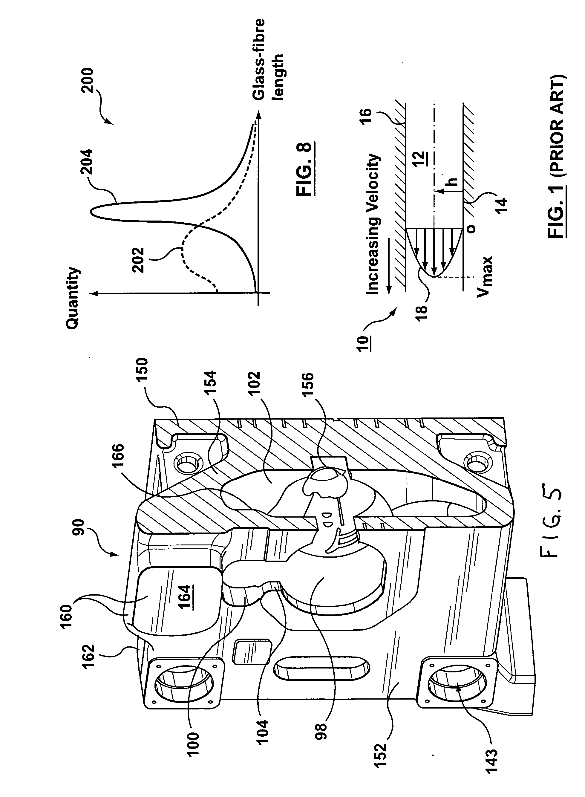
[0047] Referring to FIG. 1, there is shown a graphical representation 10 of flow velocities and related shear rates in a typical channel 12. A velocity (vmax) at a centre of the channel 12 is at a maximum, whereas velocities at sides 14, 16 are minimum. A resultant profile of a curve 18 of flow velocities in a channel therefore follows a generally symmetrical and parabolic form, with angles to tangents at each point on the curve providing a shear rate, γ, that can (for Newtonian fluids) be simplistically represented as: γ=velocity,vchannel⁢ ⁢height,h

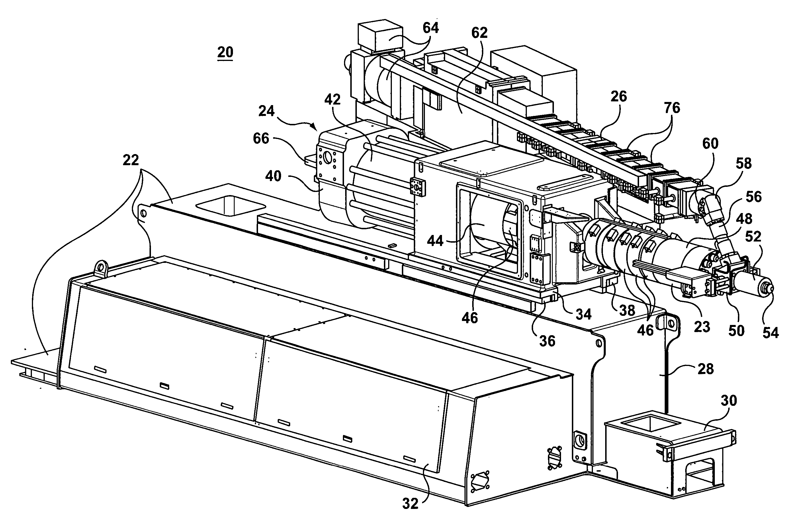
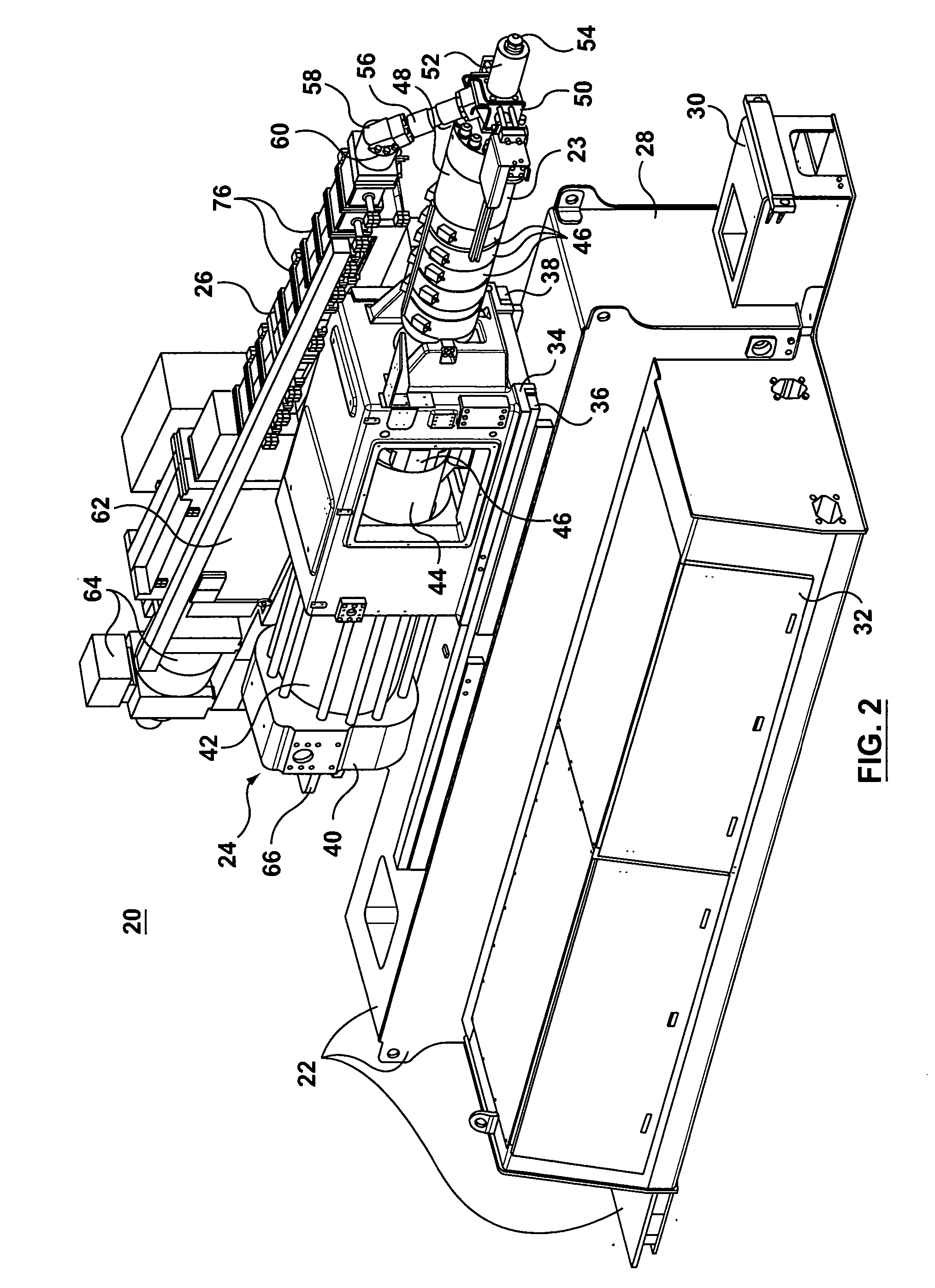
[0048]FIG. 2 is a perspective view of a two-stage injection unit assembly 20 according to a preferred embodiment of the present invention. The injection unit sub-assembly 20 is for an in-line compounding machine, the significant features of which are shown in FIG. 4). Conventionally, a machine base assembly 22 includes a solid frame that supports both a shooting pot sub-assembly 24 (realized by an injection unit and barrel) as well as a...


PUM

PropertyMeasurementUnit
Lengthaaaaaaaaaa
Massaaaaaaaaaa
Massaaaaaaaaaa

Abstract

In a molding machine (130), exemplified in FIG. 4, lateral and angled offsetting of a twin screw extruder (26) from a shooting pot assembly (24) permits shortening of a transfer channel (56). To additionally reduce shear effects arising from melt residence time a nozzle adaptor (52), the transfer channel (56) is located within a hollow cone (102) of a platen (90), the hollow cone (102) typically formed by an arch-shaped intermediate support structure (154) coupling together front (150) and rear (152) walls of the platen (90). To address bulk material removal brought about by the introduction of a barrel head, transfer channel (56) and extruder barrel tip within the hollow cone (102), reinforcement of an upper region of the rear wall (152) of the platen (90) is accomplished using a cross-member (160, 164). In an in-line compounding application, decreased lengths for the transfer channel (56) and nozzle adaptor (52) both reduce shear effects on the melt (by decreasing melt residence time) and thus an increased average fibre length in a molded part is achieved.

Description

BACKGROUND OF THE INVENTION [0001] This invention relates, in general, to a molding machine and is particularly, but not exclusively, applicable to an in-line compounding machine that operates to introduce and distribute additives into a melt produced by a screw extruder. The present invention further relates to the production of a molded part containing, typically, long-glass fibres and an apparatus and mechanism for addressing undesirable shear-related processing effects in a plastic melt. SUMMARY OF THE PRIOR ART [0002] Injection molding technology supports the production of molded parts of varying sizes, e.g. bottle preforms, car bumpers and component housings. The benefits of injection molding technology include cycle speed, consistently reproducible part quality and cost. Especially in the context of plastic injection molding, parts are relatively light when compared with cast steel or machined metal alternatives. [0003] In relation to large-sized, lightweight molded parts or ...

Claims


Application Information

Patent Timeline
IPC IPC(8): B29C45/00B29C48/40
CPCB29C45/0005B29K2105/08B29C45/1761B29C45/1773B29C45/54B29C47/0014B29C47/0023B29C47/0033B29C47/08B29C47/10B29C47/40B29C49/06B29C2045/466B29K2105/12B29L2031/3044B29C45/1744B29C48/05B29C48/09B29C48/13B29C48/25B29C48/285B29C48/40B29C2949/0715
Inventor UJMA, ANDREASJUARISTI-TELLO, ENRIQUE
Owner HUSKY INJECTION MOLDING SYST LTD
Why Eureka
Try Eureka