Multimodal polyethylene compositions and pipe made from same
- Summary
- Abstract
- Description
- Claims
- Application Information
AI Technical Summary
Benefits of technology
Problems solved by technology
Method used
Image


Examples
example 1
[0087] Alumina A, from W.R. Grace Company, was impregnated to incipient wetness with an aqueous solution of ammonium sulfate. Typically, the alumina had a surface area of about 330 m2 / gram and a pore volume of about 1.3 cc / gram. The amount of ammonium sulfate used was equal to 20% of the starting alumina. The volume of water used to dissolve the ammonium sulfate was calculated from the total pore volume of the starting sample (i.e. 2.6 mLs of water for each gram of alumina to be treated). Thus, a solution of about 0.08 grams of ammonium sulfate per mL of water was employed. The resulting wet sand was dried in a vacuum oven overnight at 120° C., and then screened through a 35 mesh screen. Finally, the material was activated in a fluidizing stream of dry air at 550° C. for 3 hours, in the case of bench scale samples, or 6 hours, for the larger pilot plant samples. The samples were then stored under nitrogen.
example 2
[0088] The metallocenes used in the various examples were purchased or prepared as follows. While certain preparations are set forth herein, it should be understood that the metallocenes used in accordance with this invention can be prepared using numerous techniques. Several techniques are described in U.S. patent application Ser. No. 10 / 876,948, filed Jun. 25, 2004 and entitled “Improved Synthesis Of Ansa-Metallocenes And Their Parent Ligands In High Yield,” incorporated by reference herein in its entirety. Also, metallocene compounds can be prepared as described in U.S. patent application Ser. Nos. 10 / 876,891 and 10 / 876,930, both filed on Jun. 25, 2004 and entitled “Polymerization Catalysts For Producing Polymers With Low Levels Of Long Chain Branching,” U.S. patent application Ser. No. 11 / 208,077, filed Aug. 19, 2005 and entitled “Polymerization Catalysts and Process for Producing Bimodal Polymers in a Single Reactor,” and U.S. patent application Ser. No. 11 / 209,006, filed Aug. ...
example 3
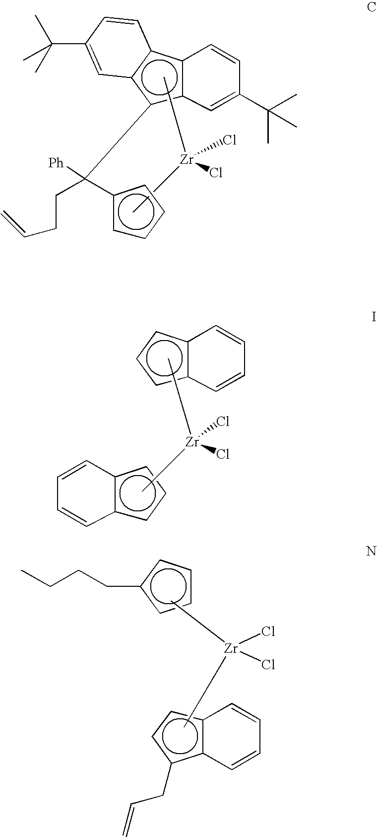
[0096] Bench Scale polymerization was performed in a 1 gallon Autoclave Engineers reactor. Solutions of Phenyl-3-butenylmethylidene(η5-cyclopentadienyl)(η5-9-2,7-di-tert-butylfluorenyl)-zirconium dichloride were made at 1 mg / mL in toluene and used as follows. To a Wheaton bottle containing 58 mg of sulfated chemically treated solid oxide (CTSO sulfated with H2SO4), 45 mLs of dry heptane were added followed by the specified amount of either 25wt. % TIBAL (triisobutylaluminum) or 19 wt. % TNBAL (tri-n-butylaluminum) and then 1 mg (1 mL of solution) of metallocene in toluene. After contacting for 15 min, the slurry was charged to a dry autoclave under isobutane purge. Following addition of 2 Liters of isobutane, the slurry was stirred while raising the temperature to the set point. Once the temperature was within 5 degrees of the set point, ethylene was added and fed on demand during the run to maintain the desired total pressure. At the end of each run, volatiles were vented from the ...
PUM
| Property | Measurement | Unit |
|---|---|---|
| Temperature | aaaaa | aaaaa |
| Density | aaaaa | aaaaa |
| Density | aaaaa | aaaaa |
Abstract
Description
Claims
Application Information
 - Generate Ideas
- Intellectual Property
- Life Sciences
- Materials
- Tech Scout
- Unparalleled Data Quality
- Higher Quality Content
- 60% Fewer Hallucinations
Browse by: Latest US Patents, China's latest patents, Technical Efficacy Thesaurus, Application Domain, Technology Topic, Popular Technical Reports.
© 2025 PatSnap. All rights reserved.Legal|Privacy policy|Modern Slavery Act Transparency Statement|Sitemap|About US| Contact US: help@patsnap.com