Electronic assembly video inspection system

a video inspection system and electronic assembly technology, applied in image analysis, printed circuit testing, image enhancement, etc., can solve problems such as the inability to detect defects the inability to test whether defects exist on freshly assembled printed circuit boards, and the inability to properly direct repair. , to achieve the effect of improving the throughput of automatic assembly mechanisms, improving defect detection, and efficient repair

Inactive Publication Date: 2007-03-01
EASTON HUNT CAPITAL PARTNERS
View PDF2 Cites 16 Cited by
  • Summary
  • Abstract
  • Description
  • Claims
  • Application Information

AI Technical Summary

Benefits of technology

[0015] The objects of this invention are: to improve defect detection in the inspection and testing of electronic components assemblies; to more efficiently direct repair; to allow for the monitoring over time of the quality of inspected boards, in order to improve the throughput of automatic assembly mechanisms; to allow portability of the inspection device to various points on the assembly line and off the assembly line altogether for manual testing.

Problems solved by technology

At each step there is a potential for errors to occur which result in a defective board.
Some of the potential printed circuit board assembly defects include: circuit board defects such as opens and shorts on the traces; placement defects wherein components are missing, of the wrong type, incorrectly oriented, or misaligned; solder defects in amount and placement which can result in solder bridges on the leads or tomb-stoning of components caused by solder contraction during curing; and other defects such as damage caused by mechanical mishandling.
Previous procedures and devices for testing whether defects exist on freshly assembled printed circuit boards suffer from various drawbacks.
Human testing and inspection is costly, slow and subject to a high degree of inaccuracy.
The devices used by human testers are typically heavy, bulky, and not readily portable.
Electronic in-circuit testing suffers from being slow and highly iterative in order to pinpoint the location of a defect and often cannot detect the most common manufacturing errors.
However, a particular piece of automated test apparatus is usually designed to test a specific type of board, specific defects, and / or only at a specific point in the assembly.
Current automatic visual or other electromagnetic radiation based inspection systems suffer from similar drawbacks.
However, high resolution x-ray inspection is expensive and time consuming, and potentially hazardous to nearby human operators.
These systems are relatively low resolution and hence slow.
In addition, monochrome intensity comparisons are prone to inaccuracies where adjacent features have similar intensities.
These requirements increase the cost and lower the portability of the system.

Method used


Image

  • Electronic assembly video inspection system
  • Electronic assembly video inspection system
  • Electronic assembly video inspection system

Examples


Embodiment Construction

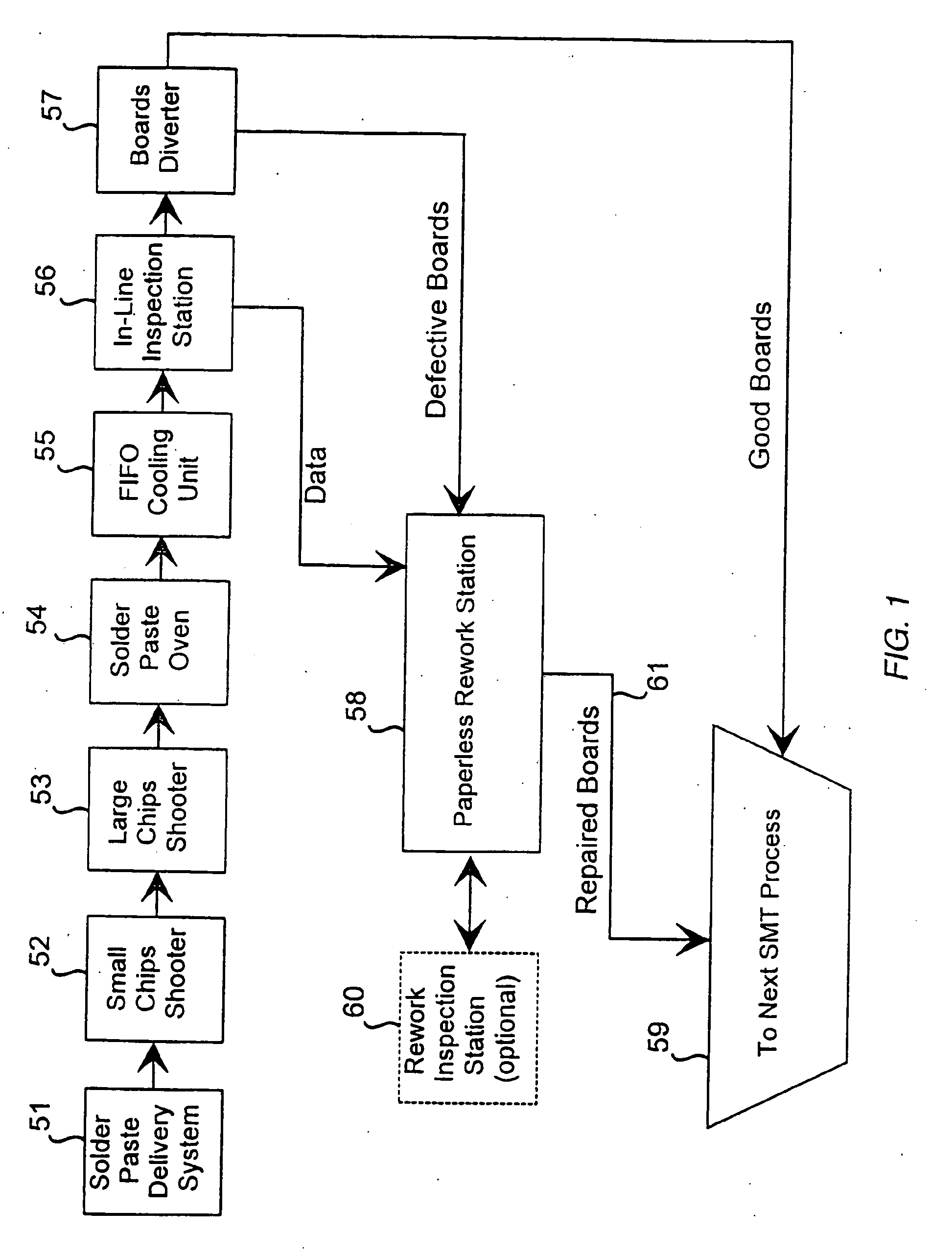
[0025] Referring now to the drawing, there is shown in FIG. 1 a functional block diagram of a typical SMT assembly line where printed circuit boards are assembled in a series of processing stations. Circuit boards move from solder paste application station 51, to one or more chip shooter stations 52, 53 and to an oven 54 for curing. An optional first-in-first-out (“FIFO”) buffer station 55 may be used to connect stations which complete their tasks more sporadically, or in different groupings of boards. In the present embodiment the FIFO station 55 is used as a cooling station for groups of boards exiting the curing oven 54 before entering the inspection station 56.

[0026] It should be noted that the inspection station 56 may be located between any one of the stations of the assembly process or as a stand alone manually loaded station. However, the preferred location is immediately after the boards have become fully populated, so as to prevent any further processing of defective boar...


PUM


Abstract

An apparatus for automatically assessing the quality of a printed circuit board assembly using digitized video image analysis. The apparatus integrates with existing relatively low precision automated surface mount technology (“SMT”) manufacturing systems as an inspection station insertable at various steps in the assembly process or as a separate manually loaded station. The inspection station includes a high resolution video imaging system and a video image analyzer comprising an onboard master computer that generates control signals to reposition the camera mounted within a screen on a movable carriage and / or reposition the circuit board, and adjust the lighting; and generates individual board status data to be archived, graphically displayed on monitors or otherwise utilized by a rework station.

Description

PRIOR APPLICATION [0001] This is a divisional application of Ser. No. 11 / 398,020 filed Apr. 4, 2006, a divisional application of Ser. No. 10 / 838,960 filed May 4, 2004, now U.S. Pat. No. 7,043,070, issued May 9, 2006, a divisional of Ser. No. 10 / 682,262 filed Oct. 8, 2003, a divisional of Ser. No. 09 / 486,234 filed Feb. 23, 2000 now U.S. Pat. No. 6,681,038 issued Jan. 20, 2004, a continued prosecution of PCT / US98 / 21383 filed Oct. 8, 1998, which claims the benefit of Ser. No. 08 / 947,756 filed Oct. 9, 1997, which claims the benefit of provisional application Ser. No. 60 / 028,451 filed Oct. 9, 1996.FIELD OF THE INVENTION [0002] This invention relates to automated assembly mechanisms for electronic components, quality assurance, and more particularly to devices used in assessing whether components have been assembled adequately. BACKGROUND OF THE INVENTION [0003] The ever-increasing miniaturization of electronic components modules and assemblies and the market pressures for cost reduction ...

Claims


Application Information

Patent Timeline
Patent Type & Authority Applications(United States)
IPC IPC(8): G06K9/00
CPCG01R31/2808H05K13/08G06T2207/30141G06T7/0004H05K13/083
Inventor VILELLA, JOSEPH L.
Owner EASTON HUNT CAPITAL PARTNERS
Why Eureka
Try Eureka