

Membrane-mediated electropolishing
a membrane-mediated electropolishing and electropolishing technology, applied in the direction of flexible wheel, manufacturing tools, lapping machines, etc., can solve the problems of incompatible mechanically fragile materials, high cost of cmp, and hazardous waste products
- Summary
- Abstract
- Description
- Claims
- Application Information
AI Technical Summary
Benefits of technology
Problems solved by technology
Method used
Image

Examples
example 1
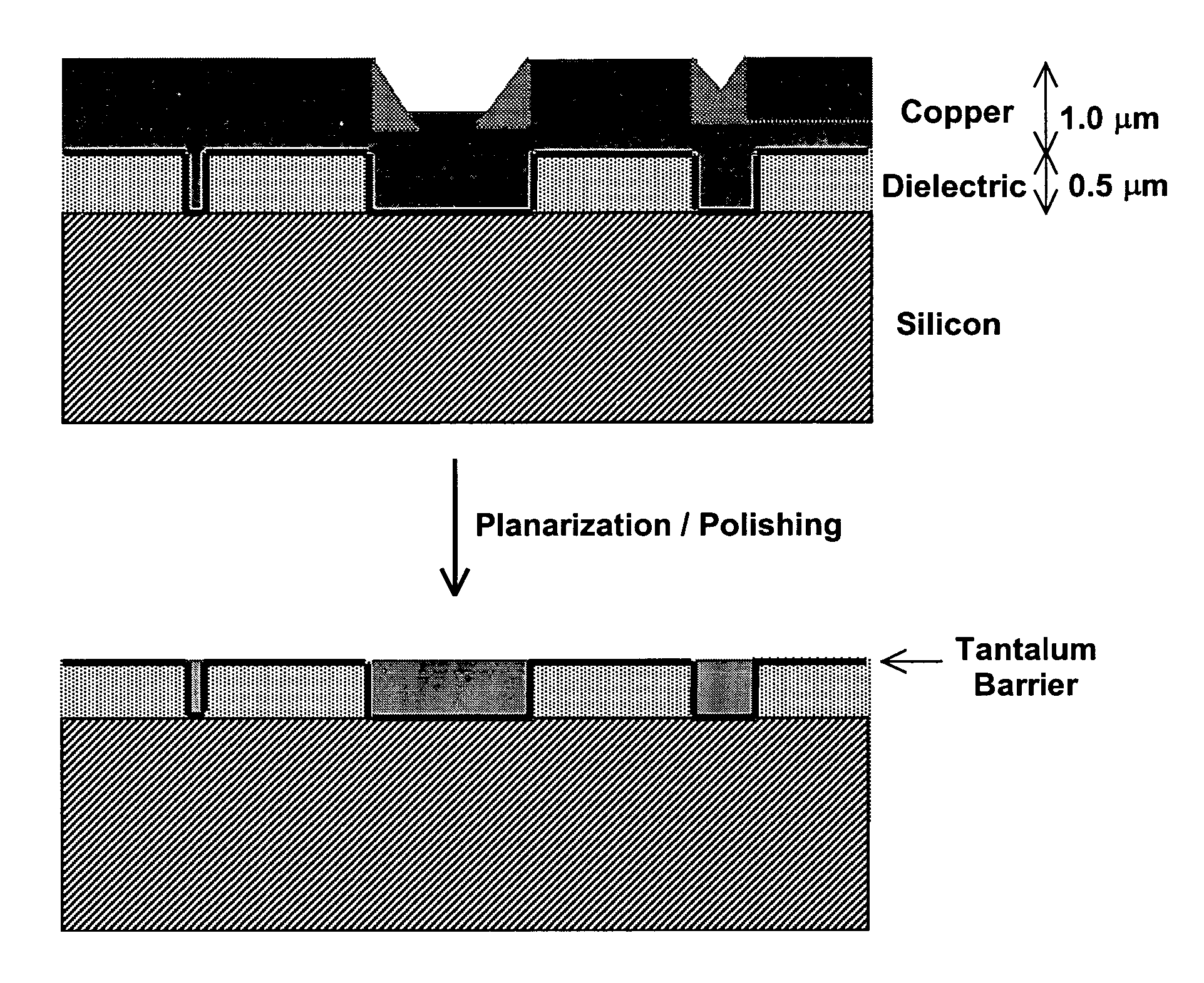
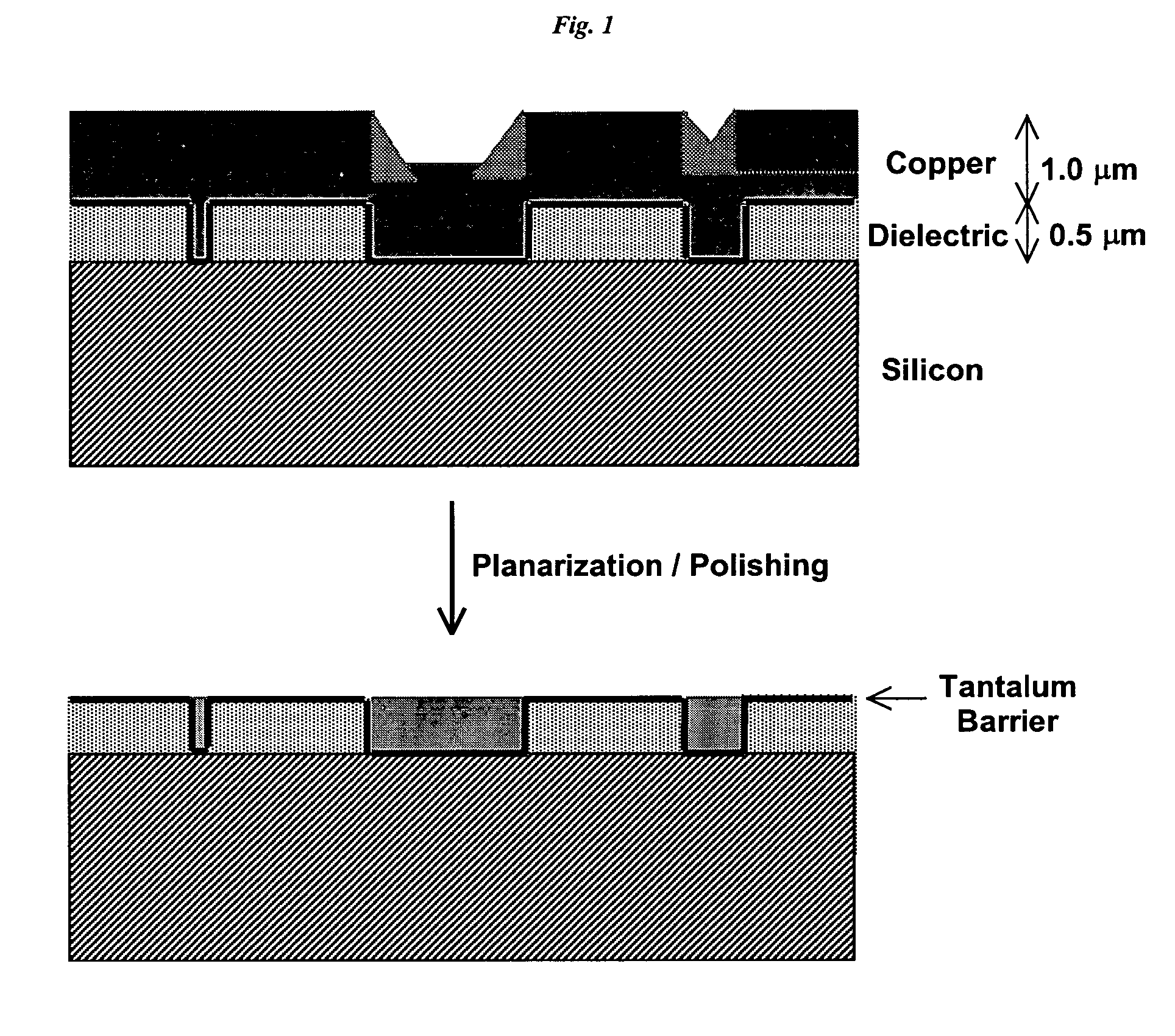
[0456] Membrane-Mediated Electropolishing of Cu Coupons
[0457] A cathode half-cell was constructed for membrane-mediated electropolishing (MMEP) whose cross-section is shown schematically in FIG. 3. The half-cell comprised a polypropylene base (1) bolted to a stainless steel faceplate (2) which framed an opening approximately 1.0 cm×2.5 cm. This opening was covered by a piece of Nafion® membrane (4) (NE1135, 3.5 mil thick) sealed against the faceplate by means of a silicone rubber gasket (3) approximately 0.5 cm thick. A piece of copper foil (6) was sealed to the base and electrically connected to a wire on the outside of the half-cell. The cavity (5) defined by base, gasket and membrane contained two ports (7) connected to Teflon® tubing (OD 1 / 16″) through which the electrolyte (0.2 M copper sulfate in 40% phosphoric acid) was continuously re-circulated by means of a peristaltic pump (not shown) from an external reservoir. Electrolyte was pumped through the half-cell at approximate...
example 2
Comparison of Membrane-Mediated and Conventional Electropolishing
[0460] Two copper coupons (1.5″×2.0″) were milled as in Example 1 and then masked with tape so that only an area of 0.71 cm2 was exposed. One of these coupons was polished by MMEP using the same procedure as in Example 1. The second coupon was polished by the conventional electropolishing (EP) method. For EP a silicone rubber gasket ⅜″ thick was used to separate the work piece from a sheet of copper foil which served as the cathode. A cylindrical cavity in this gasket provided a volume between the work piece and cathode filled by electrolyte solution that was continuously pumped through cavity. The area of work piece exposed to electrolyte in the EP cell was the same as that polished by the MMEP process. The same electrolyte (0.2 M Copper sulfate in 40% phosphoric acid) and the same pumping rate was used in both sets of polishing experiments. The root-mean-square roughness Rg was measured by profilometry and the resul...
example 3
Comparison of Membrane-Mediated and Conventional Electropolishing for Planarizing Surfaces with Large-k Features
[0463] A copper coupon was polished to a mirror finish using jeweler's rouge, then laminated to a dry-film photoresist (Riston® 9415, E.I. Dupont de Nemours and Company, Inc., Wilmington, Del.). The photoresist film was covered with a lithographic negative patterned with 100 micron lines interspersed with 100 micron spaces, and then exposed and developed under conditions recommended by the manufacturer (DuPont Riston® Printed Circuit Materials, RD 1, New James St., Towanda, Pa. USA 18848-9784). The exposed areas on the coupon were etched for 1 minute in a 5% solution of sodium monopersulfate (Sigma-Aldrich, Milwaukee, Wis.), followed by conventional electropolishing at 2.0 V and 1.5 coul / cm2 (as described in Example 2). The resist mask was then removed by soaking in dichloromethane, leaving a corrugated surface with alternating 100 micron trenches and 100 micron plateaus....
PUM
| Property | Measurement | Unit |
|---|---|---|
| Fraction | aaaaa | aaaaa |
| Fraction | aaaaa | aaaaa |
| Time | aaaaa | aaaaa |
Abstract
Description
Claims
Application Information