Apparatus for active programmable matrix devices

a programmable matrix and active technology, applied in the field of active programmable matrix devices, can solve the problems of many techniques that are limited in their application, require a high degree of accuracy, and are difficult to achieve the effects of effective interrogation, high target mobility rate, and high ionic strength

Inactive Publication Date: 2007-03-08
GAMIDA FOR LIFE
View PDF2 Cites 7 Cited by
  • Summary
  • Abstract
  • Description
  • Claims
  • Application Information

AI Technical Summary

Benefits of technology

[0021] The device is able to control and actively carry out a variety of assays and reactions. Analytes or reactants can be transported by free field electrophoresis to any specific micro-location where the analytes or reactants are effectively concentrated and reacted with the specific binding entity at the micro-location. In the case of hybridization analysis, the sensitivity for detecting a specific analyte or reactant is improved because hybridization reactants are concentrated at a specific microscopic location. Any unbound analytes or reactants can be removed by reversing the polarity of a micro-location. Thus, the device also improves the specificity of the reactions. Basic devices for nucleic acid hybridization and other analyses are alternatively referred to as APEX devices, which stands for addressable programmable electronic matrix.
[0022] In one aspect of this invention, the APEX device is utilized with a fluidic system in which a sample is flowed over the APEX device during operation. In the preferred embodiment, the fluidic system includes a flow cell and a liquid-waste containment vessel. The sample is provided to the input to the flow cell and directed across the active areas of the APEX system. Preferably, a defined volume is provided within the flow cell, preferably in the range from 5 to 10 microliters. A flowing sample over the active detection device provides important advantages in the hybridization analysis of dilute, concentrated and / or relatively complex DNA samples. For example, if the total sample volume is relatively large compared to the same chamber volume, flowing of the sample provides more complete analysis of the entire sample. Alternatively, where the sample volume is relatively small, and / or the DNA is relatively concentrated, dilution is indicated in order to reduce the viscosity of the sample.
[0027] A controller for the device (or system) provides for individual control of various aspects of the device. When an APEX device or chip containing addressable microscopic locations is utilized, the controller permits individual microlocations to be controlled electronically so as to direct the transport and attachment of specific binding entities to that location. The device may carry out multi-step and multiplex reactions with complete and precise electronic control, preferably under control of a microprocessor based component. The rate, specificity, and sensitivity of multi-step and multiplex reactions are greatly improved at the specific microlocations on the device. The controller interfaces with a user via input / output devices, such as a display and keyboard input. Preferably, a graphical user interface is adapted for ease of use. The input / output devices are connected to a controller, which in turn controls the electrical status of the addressable electronic locations on the system. Specifically, the controller directs a power supply / waveform generator to generate the electronic status of the various microlocations. Optionally, an interface is used between the power supply / waveform generator and the APEX device or system. The interface preferably comprises a bank of relays subject to the controller via a multifunction input / output connection. The relays preferably serve to connect the power supply / waveform generator to the APEX device by controlling the connection as to its polarity, the presence or absence of a connection and the amount of potential or current supply to the individual location. The controller preferably controls the illumination source directed at the hybridization system. A detector, image processing and data analysis system are optically coupled to the APEX device. In the preferred embodiment, a fluorescent microscope receives and magnifies the image from the hybridization events occurring on the various micro-locations of the device. The emissions are optically filtered and detected by a charge coupled device (CCD) array or microchannel plate detector. The image is then stored and analyzed. Preferably, the results are displayed to the user on the monitor.
[0031] Electronic control of the individual microlocations may be done so as to control the voltage or the current. When one aspect is set, the other may be monitored. For example, when voltage is set, the current may be monitored. The voltage and / or current may be applied in a direct current mode, or may vary with time. For example, pulsed currents or DC biases may be advantageously utilized. The pulsed system may be advantageously utilized with the fluidic system, especially the flow cell design. By coordinating the pulse sequence and flow rate, the sample can be more effectively interrogated throughout the sample volume. Additionally, even for non-flow situations, such as where there are relatively high amounts of non-target material, e.g., DNA, which without pulsing might overwhelm the activated test sites. Pulse techniques generally result in higher target mobility rates at higher ionic strength, reduced probe burn-out effects, improved hybridization efficiencies, improved discrimination of point mutations and enhanced DNA fingerprinting.
[0032] In yet another aspect of this invention, it has been surprisingly discovered that the fluorescence signal obtained during the electronic denaturation of DNA hybrids is perturbed at or around electronic and power levels which are associated with dehybridization. Specifically, the fluorescence signal perturbation results in a rise or spike in fluorescence intensity prior to dehybridization of fluorescently labelled probes from a capture sequence attached to an APEX pad. The power level, amplitude and slope of this fluorescence spike provide analytical tools for diagnosis. The combination of the fluorescence perturbation with other measurements also indicative of the hybridization match / mismatch state, such as consideration of the electronic melting (50% fluorescence decrease during electronic stringency control) can in combination provide a more efficient and reliable hybridization match / mismatch analysis.
[0039] It is yet another object of this invention to provide a system which is capable of manufacture using conventional techniques, with high efficiencies and low cost.

Problems solved by technology

They are often complex and time consuming, and generally require a high degree of accuracy.
Many a technique is limited in its application by a lack of sensitivity, specificity, or reproducibility.
For example, these problems have limited many diagnostic applications of nucleic acid hybridization analysis.
Unfortunately, this procedure is long and arduous.
All these procedures are time consuming, relatively complicated, and add significantly to the cost of a diagnostic test.
The theory is stated to be that there is electron transfer to the DNA at the interface of an electrode, which effectively weakens the double-stranded structure and results in separation of the strands.
While amplification results in an enormous number of target nucleic acid sequences that improves the subsequent direct probe hybridization step, amplification involves lengthy and cumbersome procedures that typically must be performed on a stand alone basis relative to the other substeps.
Substantially complicated and relatively large equipment is required to perform the amplification step.
Both formats have the fundamental problems of direct probe hybridizations and additional difficulties related to multiplex hybridizations.
However, Southern did not address how to achieve optimal stringency condition for each oligonucleotide on an array.
Even when detection methods have very high intrinsic sensitivity, detection of hybridization events is difficult because of the background presence of non-specifically bound materials.
A number of other factors also reduce the sensitivity and selectivity of DNA hybridization assays.
However, with small geometries, such as those below 2 millimeters, and especially those on the order of 500 microns or less in size of the region of interest, the conventional approaches to fluorometer design have proved inadequate.
Further, because it is usually desirable to maximize the detectable area, the size of the optical components required to achieve these goals in relation to their distance from the region of interest becomes important, and in many cases, compromises the performance obtained.
Generally, the prior art processes have been extremely labor and time intensive.
For example, the PCR amplification process is time consuming and adds cost to the diagnostic assay.
Multiple steps requiring human intervention either during the process or between processes is suboptimal in that there is a possibility of contamination and operator error.
Further, the use of multiple machines or complicated robotic systems for performing the individual processes is often prohibitive except for the largest laboratories, both in terms of the expense and physical space requirements.
However, for the reasons stated above, these techniques are “piece-meal” and limited.
These various approaches are not easily combined to form a system which can carry out a complete DNA diagnostic assay.
Despite the long-recognized need for such a system, no satisfactory solution has been proposed previously.

Method used


Image

  • Apparatus for active programmable matrix devices
  • Apparatus for active programmable matrix devices
  • Apparatus for active programmable matrix devices

Examples


Embodiment Construction

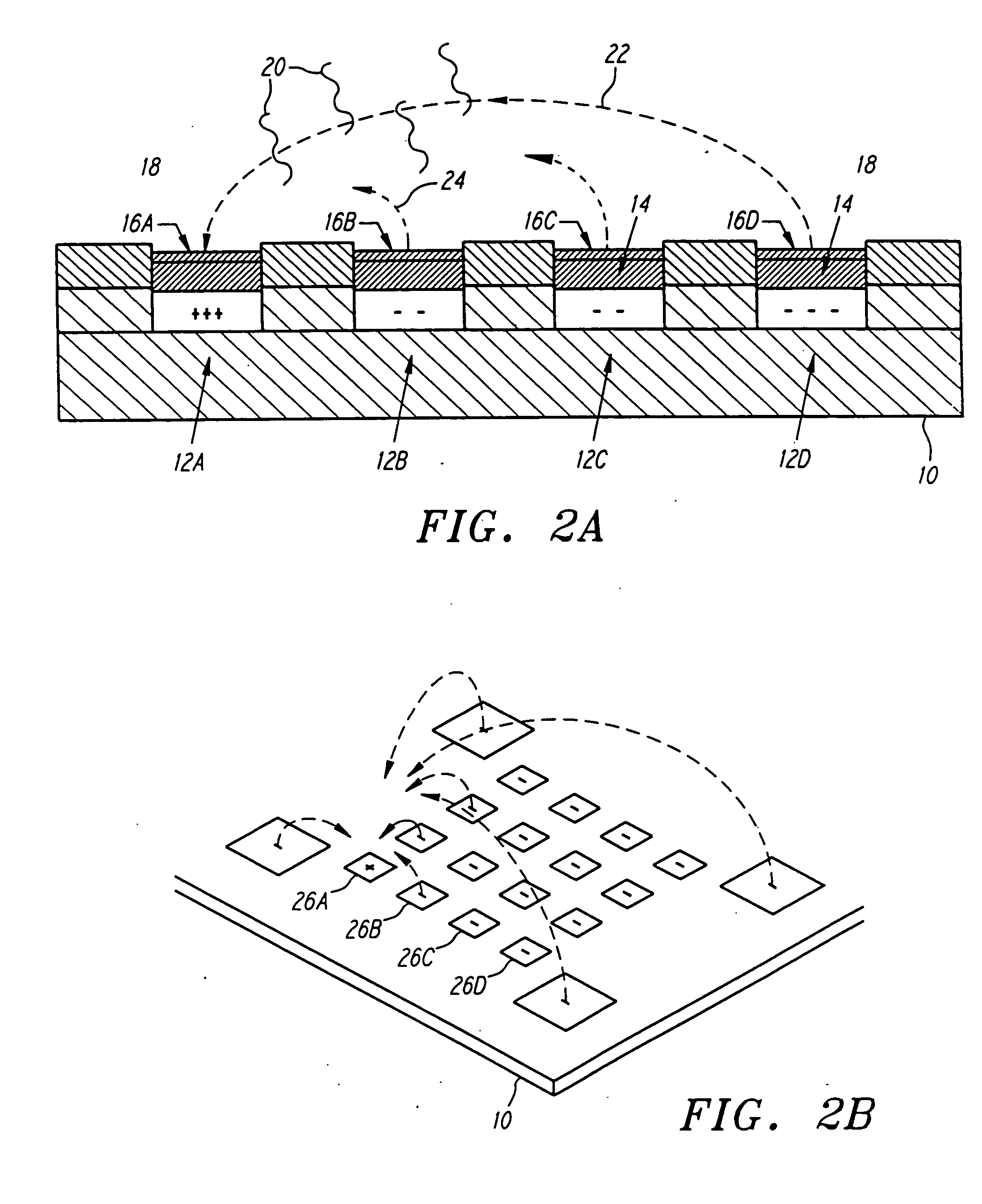
[0063]FIGS. 2A and 2B illustrate a simplified version of the active programmable electronic matrix hybridization system for use with this invention. Generally, a substrate 10 supports a matrix or array of electronically addressable microlocations 12. For ease of explanation, the various microlocations in FIG. 2A have been labelled 12A, 12B, 12C and 12D. A permeation layer 14 is disposed above the individual electrodes 12. The permeation layer permits transport of relatively small charged entities through it, but precludes large charged entities, such as DNA, from contacting the electrodes 12 directly. The permeation layer 14 avoids the electrochemical degradation which would occur in the DNA by direct contact with the electrodes 12. It further serves to avoid the strong, non-specific adsorption of DNA to electrodes. Attachment regions 16 are disposed upon the permeation layer 14 and provide for specific binding sites for target materials. The attachment regions 16 have been labelled...


PUM

PropertyMeasurementUnit
temperaturesaaaaaaaaaa
sizeaaaaaaaaaa

Abstract

A system for performing molecular biological diagnosis, analysis and multistep and multiplex reactions utilizes a selfaddressable, selfassembling microelectronic system for actively carrying out controlled reactions in microscopic formats. Preferably, a fluidic system flow a sample across an active area of the biochip, increasing diagnostic efficiency. Preferably, the fluidic system includes a flow cell having a window. Pulsed activation of the electrodes of the biochip are advantageously employed with the fluidic system, permitting more complete sampling of the materials within the biological sample. An improved detection system utilizes a preferably coaxially oriented excitation fiber, such as a fiber optic, disposed within a light guide, such as a liquid light guide. In this way, small geometric systems may be fluorescently imaged. A highly automated DNA diagnostic system results. Perturbation of the fluorescence signal during electronic denaturation is detailed and analyzed for analytical and diagnostic purposes. Such fluorescence perturbation information is combined with other information to provide improved analysis. DNA fingerprinting uses hybridizing DNA fragments of a given length and a capture sequence at a test site and then determining the level of reverse bias necessary to affect the hybridization, such as to dehybridize, and determine the length of the DNA.

Description

RELATED APPLICATION INFORMATION [0001] This application is a continuation of U.S. application Ser. No. 09 / 597,866, filed Jun. 20, 2000, entitled “APPARATUS FOR ACTIVE PROGRAMMABLE MATRIX DEVICES,” now allowed, which is a continuation of U.S. application Ser. No. 09 / 141,286, filed Aug. 27, 1998, entitled “METHOD FOR FINGERPRINTING UTILIZING AN ELECTRONICALLY ADDRESSABLE ARRAY,” issued as U.S. Pat. No. 6,245,508, which is a continuation of U.S. application Ser. No. 08 / 534,454, filed Sep. 27, 1995, entitled “METHODS FOR HYBRIDIZATION ANALYSIS UTILIZING ELECTRICALLY CONTROLLED HYBRIDIZATION,” issued as U.S. Pat. No. 5,849,486, which is a continuation-in-part of application Ser. No. 08 / 304,657, filed Sep. 9, 1994, entitled “MOLECULAR BIOLOGICAL DIAGNOSTIC SYSTEM,” issued as U.S. Pat. No. 5,632,957, which is a continuation-in-part of application Ser. No. 08 / 271,882, filed Jul. 7, 1994, entitled “METHODS FOR ELECTRONIC STRINGENCY CONTROL,” now issued as U.S. Pat. No. 6,017,696, which is a ...

Claims


Application Information

Patent Timeline
Patent Type & Authority Applications(United States)
IPC IPC(8): C12Q1/68
CPCB01J2219/00317G01N2035/00158B01J2219/00608B01J2219/00621B01J2219/00637B01J2219/00644B01J2219/00653B01J2219/00659B01L3/5027B01L3/502707B01L2200/0647B01L2200/0689B01L2200/12B01L2300/0636B01L2300/0645B01L2300/0877B01L2400/0421C07H21/00B01J2219/00418
Inventor HELLER, MICHAEL JAMESO'CONNELL, JAMES PATRICKJUNCOSA, ROBERT DAVIDSOSNOWSKI, RONALD GEORGEJACKSON, THOMAS RATCLIFFE
Owner GAMIDA FOR LIFE
Why Eureka
Try Eureka