Magneto-resistance element and thin film magnetic head with improved heat reliability

a thin film magnetic head and magnetic resistance element technology, applied in the field of thin film magnetic head, can solve the problems of limited reliability of operating current, reduced area, and reduced element height, and achieve the effect of improving heat reliability and high magnetic resistance change ra

Active Publication Date: 2007-03-15
TDK CORPARATION
View PDF9 Cites 12 Cited by
  • Summary
  • Abstract
  • Description
  • Claims
  • Application Information

AI Technical Summary

Benefits of technology

[0020] It is an object of the present invention to provide a magneto-resistance element and a thin

Problems solved by technology

The element area is reduced by the narrowed tracks and the element height that is attendant thereon is shortened, however, in the conventional arrangement, because the heat radiation efficiency is lowered as the area is reduced, the reliability of operating current is restricted.
This MR change rate is insufficient in terms of output when practical use is considered.
On the other hand, in the dual spin valve structure that can obtain a relatively high MR change rate, since each film thickness of both the two spin valves is large, that the film thickness of the spin valve is large does not meet the requirement that the lead gap be narrow.
However,

Method used


Image

  • Magneto-resistance element and thin film magnetic head with improved heat reliability
  • Magneto-resistance element and thin film magnetic head with improved heat reliability
  • Magneto-resistance element and thin film magnetic head with improved heat reliability

Examples


embodiment 1

[0042] A magnetron-resistance element according to the present embodiment has a full-Heusler alloy represented by a composition formula of X2YZ (X is a precious metal including Cu, Y is a transition metal of Mn, V, or Ti group, and Z is any element from group III to group V) as a magnetic film. Hereinafter, the magneto-resistance element is explained in the case of a CPP-GMR element. Also, in the present embodiment, (CoXPd1-X)2MnSn is used as a Heusler alloy thin film material. In (CoXPd1-X)2MnSn, composition X is Pd, a part of composition X is replaced with Co, composition Y is Mn, and composition Z is Sn.

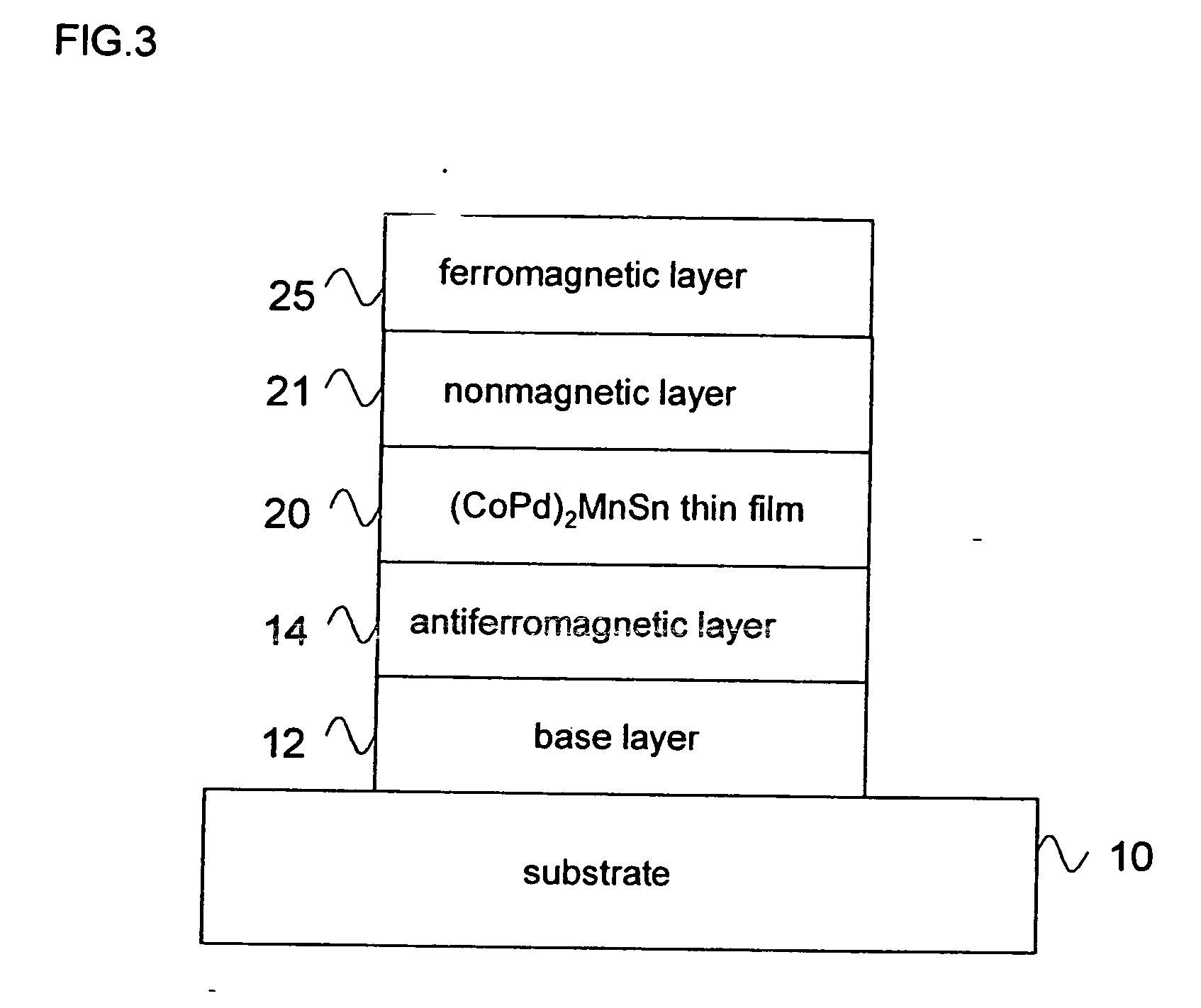
[0043]FIG. 3 is a cross-sectional view showing a structure example of a magneto-resistance element according to the present embodiment. As shown inFIG. 3, a CPP-GMR element is formed by sequentially laminating base layer 12, antiferromagnetic film 14, (CoXPd1-X)2MnSn thin film 20, nonmagnetic layer 21, and ferromagnetic layer 25 on substrate 10. In this structure, antiferromagnet...

embodiment 2

[0088] The present embodiment provides a wafer that is used to manufacture the thin film magnetic head of Embodiment 1, a head gimbal assembly having a slider provided with the thin-film magnetic head, a head arm assembly provided with the head gimbal assembly, a head stack assembly provided with the head arm assembly, and a hard disk drive having a slider provided with the thin film magnetic head. Each arrangement is explained below.

[0089] Explanations are given of a wafer that is used to manufacture the thin film magnetic head according to Embodiment 1.

[0090]FIG. 14 is a conceptual plan view of a wafer. Wafer 100 is partitioned into a plurality of thin film magnetic conversion element assembly 101. Thin film magnetic conversion element assembly 101 includes thin film magnetic conversion element 102 formed by laminating the MR element of Embodiment 1 and inductive magnetic conversion element, and is a work unit for applying the polishing process to form ABS. Spacing (not shown) i...


PUM


Abstract

A magneto-resistance element according to the present invention has a pinned layer whose magnetization direction is fixed; a free layer whose magnetization direction varies in accordance with an external magnetic field; and a nonmagnetic spacer layer that is arranged between the pinned layer and the free layer, at least the pinned layer or the free layer includes a layer having Heusler alloy represented by composition formula X2YZ (where X is a precious metal element, Y is a transition metal of Mn, V, or Ti group, Z is an element from group III to group V), and a part of composition X is replaced with Co, and an atomic composition ratio of Co in composition X is from 0.5 to 0.85.

Description

[0001] This application is based upon and claims the benefit of priority from Japanese Patent Application No. 2005-266968 filed on Sep. 14, 2005, the content of which is incorporated by reference. BACKGROUND OF THE INVENTION [0002] 1. Field of the Invention [0003] The present invention relates to a thin film magnetic head for a hard disk drive and a magneto-resistance element used as a reproducing unit in the thin film magnetic head. [0004] 2. Description of the Related Art [0005] As hard disk drivers become ever-denser, performance improvement in thin film magnetic heads is required. As a thin film magnetic head, there is widely used a complex thin film magnetic head made by laminating a reproducing head that has a magneto-resistance element (MR element) for reading and a recording head that has an inductive electromagnetic conversion element for writing. Currently, a magneto-resistance element that is operated by feeding a current in parallel with a film surface, which is called a...

Claims


Application Information

Patent Timeline
IPC IPC(8): G11B5/127G11B5/33
CPCB82Y10/00B82Y25/00G01R33/093H01F10/3272G11B2005/3996H01F1/408H01F10/1936G11B5/3929
Inventor SHIMAZAWA, KOJITSUCHIYA, YOSHIHIROMIZUNO, TOMOHITO
Owner TDK CORPARATION
Why Eureka
Try Eureka