Fabricating method of an active-matrix organic electroluminescent display panel

a technology of organic electroluminescent display panel and fabrication method, which is applied in the direction of optics, identification means, instruments, etc., can solve the problems of inability to enhance the luminescence efficiency the inability to design circuit interconnection, and the inability to control the brightness of the oel display panel. achieve the effect of preventing the source and drain of a tft, reducing the affection of the gate voltage to the current through th

Active Publication Date: 2007-03-22
AU OPTRONICS CORP
View PDF3 Cites 8 Cited by
  • Summary
  • Abstract
  • Description
  • Claims
  • Application Information

AI Technical Summary

Benefits of technology

[0012] This invention also intends to dispose / form the metal electrode layer on the organic function layer in an active-matrix OEL display panel and a fabricating method of the same, so that some metal atoms can be driven into the electron transporting layer during the sputtering process for forming the metal electrode layer. Therefore, the efficiency of electron injection in the OLEDs can be enhanced.
[0018] Moreover, another passivation layer can be formed on the TFTs after the TFTs are formed and before the metal electrode layers are formed. The additional passivation layer is capable of preventing a metal electrode layer from electrically connecting the source and the drain of the corresponding TFT when misalignment occurs during the patterning process of the metal electrode layers. Therefore, it is possible to prevent the source and the drain of a TFT from being shorted.
[0019] Since the cathode of an OLED is connected with the drain of a TFT in the active-matrix OEL display panels of this invention, the affection of the gate voltage to the current through the OLED can be reduced when the voltage across the TFT is shifted. Therefore, the stability of the current through the OLED can be improved.
[0020] Moreover, since an OLED in this invention can be formed by sequentially stacking a transparent conductive layer, a hole injection layer, a hole transporting layer, an emitting layer, an electron transporting layer and a metal electrode layer, some metal atoms can be driven from the metal electrode layer into the electron transporting layer during the sputtering process for forming the metal electrode layer. Therefore, the efficiency of electron injection in the OLED can be enhanced, and the luminescence efficiency of the OEL display panel can be improved.
[0021] In addition, this invention provides a new type of common anode, which consists of transparent conductive layers on the pixel regions of the substrate and a metal layer on the non-pixel region of the substrate. Therefore, the OEL display panel can make bottom light emission, and the electrical conductivity between the OLEDs can be enhanced because the metal layer has a low resistance.

Problems solved by technology

However, due to the low electrical conductivity of a-Si material, only N-type TFTs are formed in an active-matrix OEL display, and the design of circuit interconnection is therefore restricted.
However, when the voltage across the TFT is shifted, the voltage on the gate electrode will affect the voltage on the source to cause an unstable current through the OLED.
However, the OEL display element illustrated in FIG. 1 has some problems described below.
Therefore, lithium atoms are not driven into the electron transporting layer, and the luminescence efficiency of the OEL display panel cannot be enhanced.

Method used


Image

  • Fabricating method of an active-matrix organic electroluminescent display panel
  • Fabricating method of an active-matrix organic electroluminescent display panel
  • Fabricating method of an active-matrix organic electroluminescent display panel

Examples


Embodiment Construction

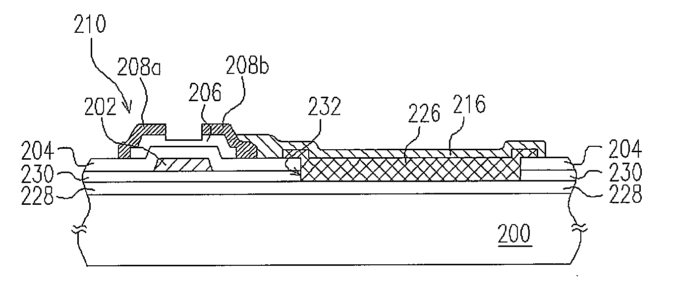
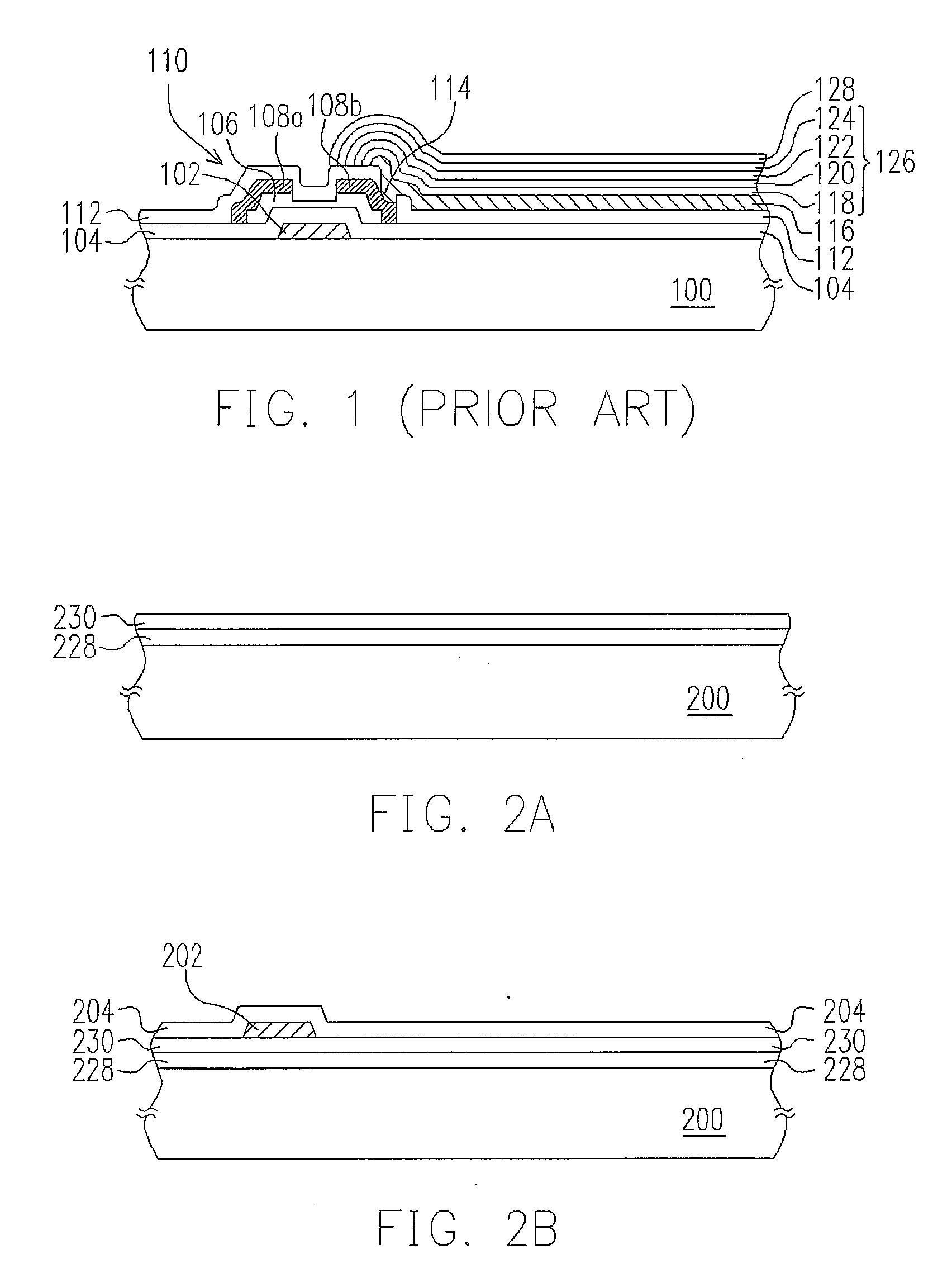
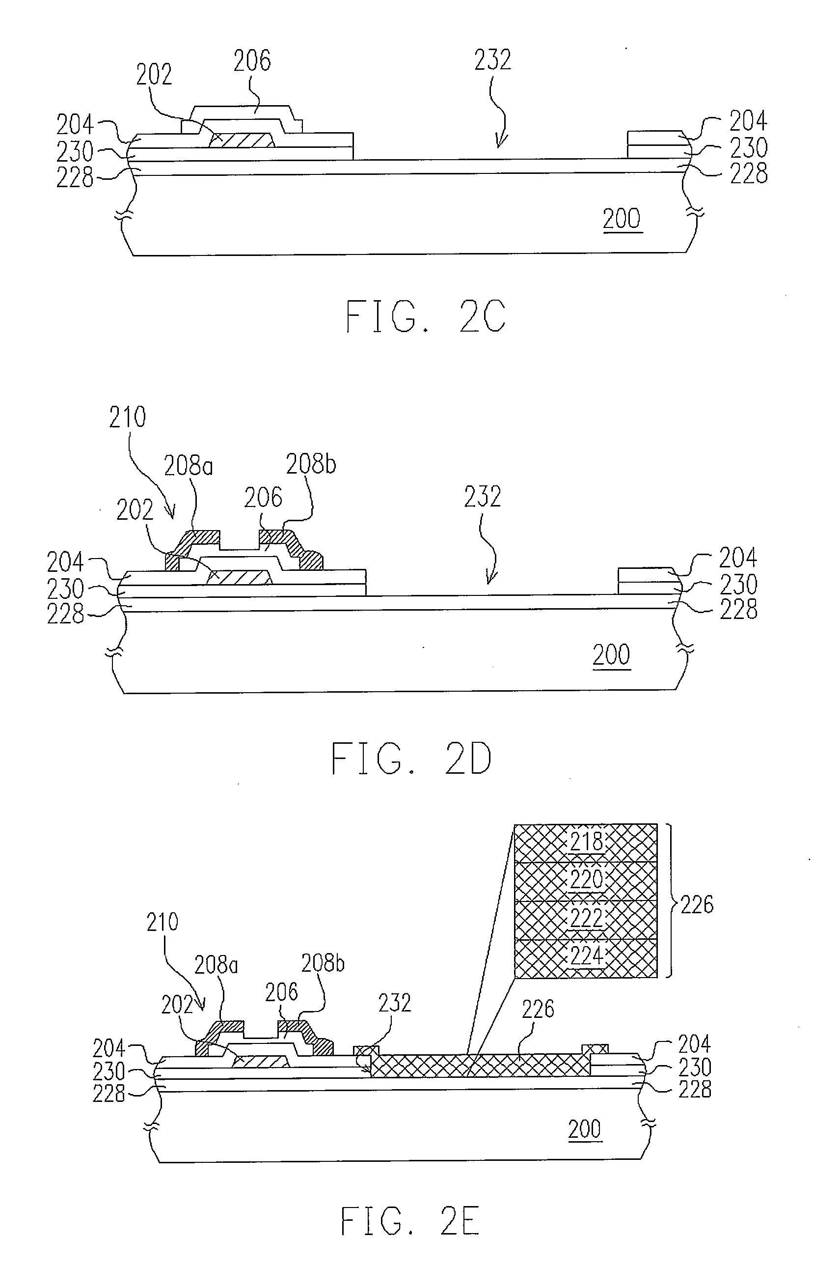
[0029]FIGS. 2A-2F illustrate a process flow of fabricating an active-matrix OEL display panel according to a preferred embodiment of this invention in a cross-sectional view. Though an OEL display panel has many OEL display elements thereon arranged as a matrix, FIGS. 2A-2F illustrate the fabrication of only one OEL display element for convenience.

[0030] Referring to FIG. 2A, a substrate 200, such as a glass substrate or a plastic substrate, is provided. A transparent conductive layer 228 is formed on the substrate 200 to serve as a common anode. The transparent conductive layer 228 includes a material such as indium tin oxide (ITO) or indium zinc oxide (IZO), and is formed with a sputtering process, for example. A blanket passivation layer 230, which includes a material such as silicon nitride, is formed on the transparent conductive layer 228 with plasma-enhanced chemical vapor deposition (PECVD), for example. The passivation layer 230 is formed to isolate the transparent conduct...


PUM

PropertyMeasurementUnit
transparentaaaaaaaaaa
transparent conductiveaaaaaaaaaa
structureaaaaaaaaaa

Abstract

A method for fabricating an active-matrix organic electroluminescent (OEL) display panel is described. A transparent conductive layer is formed on a substrate as a common anode for all organic light emitting diodes (OLED), and a passivation layer is formed on the transparent conductive layer. Thin film transistors are formed on the passivation layer to serve as an active matrix, and openings are formed in the passivation layer to expose portions of the transparent conductive layer and define pixel regions. An organic function layer is formed in each opening, and a metal electrode layer is formed on each organic function layer, wherein the metal electrode layer is electrically connected with the drain of the corresponding thin film transistor.

Description

CROSS-REFERENCE TO RELATED APPLICATION [0001] This is a divisional application of patent application Ser. No. 10 / 708,368, filed on Feb. 26, 2004, which claims the priority benefit of Taiwan patent application serial no. 92107721, filed on Apr. 4, 2003 and is now allowed. The entirety of each of the above-mentioned patent applications is hereby incorporated by reference herein and made a part of this specification.BACKGROUND OF THE INVENTION [0002] 1. Field of the Invention [0003] The present invention relates to a fabricating method of a structure of a display panel. More particularly, the present invention relates to a fabricating method of a structure of an active-matrix organic electroluminescent display panel. [0004] 2. Description of the Related Art [0005] Organic electroluminescent (OEL) displays are light, thin and readily portable like liquid crystal displays (LCD) are, but do not need an additional backlight source, and therefore are getting more and more attention in the m...

Claims


Application Information

Patent Timeline
Patent Type & Authority Applications(United States)
IPC IPC(8): H01L21/84H01L21/00G02F1/13G09F9/30H01L27/32H01L51/52H05B33/00
CPCH01L51/5212H01L27/3248H10K59/123H10K50/814
Inventor LIN, CHIAO-JU
Owner AU OPTRONICS CORP
Why Eureka
Try Eureka