
Rinse treatment method, developing treatment method and developing apparatus

Active Publication Date: 2007-03-29
TOKYO ELECTRON LTD
View PDF9 Cites 15 Cited by
  • Summary
  • Abstract
  • Description
  • Claims
  • Application Information

AI Technical Summary

Benefits of technology

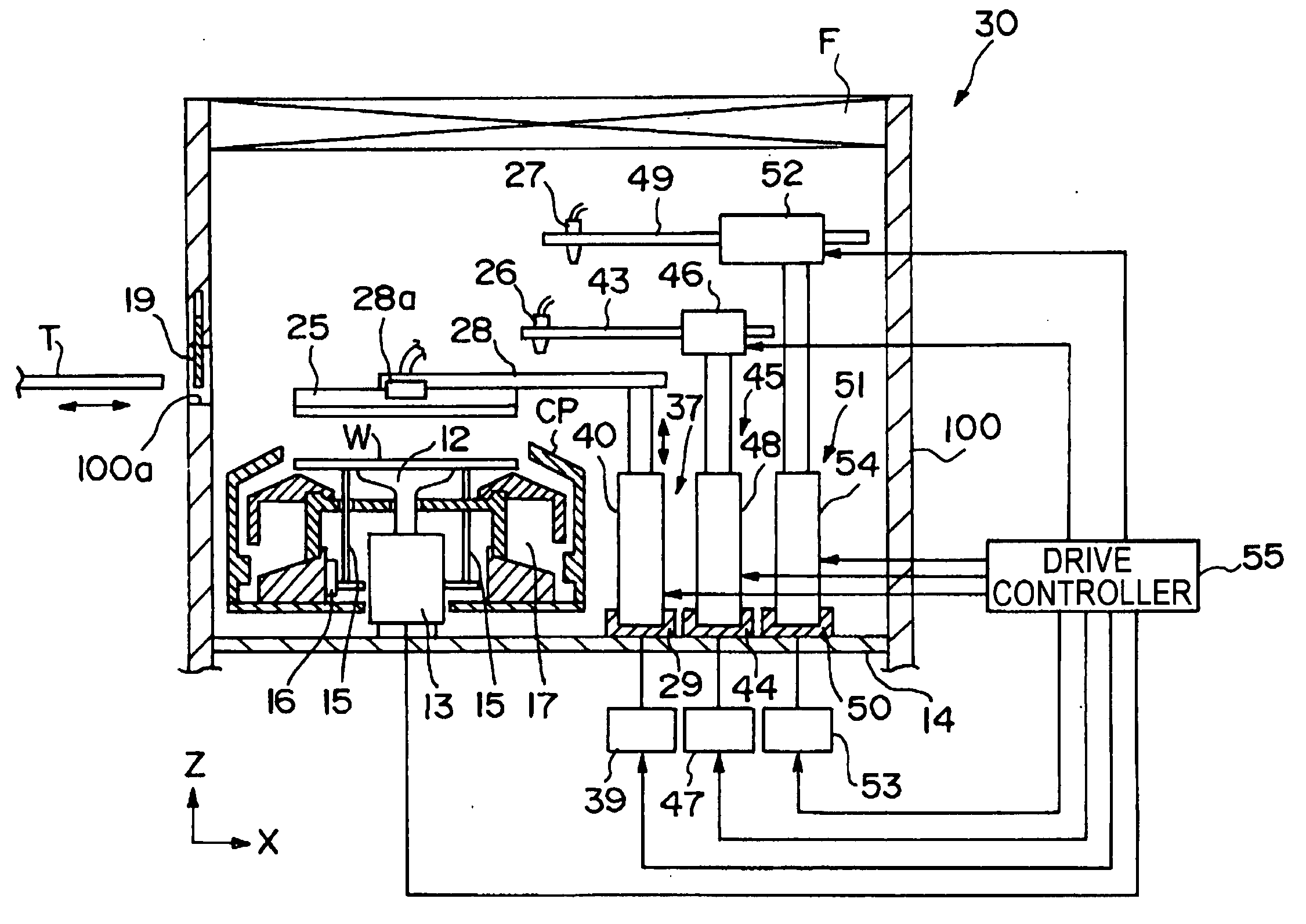
[0012] The present invention has been developed in consideration of the above-described circumstances, and its object is to make it possible, in the rinse treatment of the substrate after developing treatment, to dry the substrate without causing pattern collapse to restrain variation in the pattern line width, and to reduce the remaining precipitation-based defects to increase the productivity.
[0017] According to the present invention, the cleaning with the pure water first restrains the variation in pattern line width (CD), the cleaning with the surfactant with a high concentration then significantly removes the precipitation-based defects, and the cleaning with the surfactant with a low concentration finally restrains the pattern line width (CD) and keeps the lowered surface tension of the rinse solution.
[0018] Accordingly, the restraint of variation in the pattern line width and the removal of the precipitation-based defects are achieved, and the pattern collapse at the time of shaking-off drying is prevented. Further, the use of the surfactant allows the precipitation-based defects to be removed without extending the rinse time, resulting in prevention of a decrease in throughput to increase the productivity.
[0019] It is preferable to perform, after the step of cleaning the substrate with the second rinse solution, the steps of rotating the substrate for a predetermined time at a first rotation speed to move the rinse solution on the substrate to a periphery of the substrate; and rotating the substrate for a predetermined time at a second rotation speed higher than the first rotation speed to shake off the rinse solution moved to the periphery of the substrate to thereby dry the substrate.
[0020] This can shake off the precipitation-based defects together with the rinse solution without the periphery of the substrate from drying earlier than the other to reduce the number of precipitation-based defects remaining on the substrate after the drying processing.
[0023] According to the present invention, in the rinse treatment of the substrate after developing treatment, it is possible to dry the substrate without causing pattern collapse to restrain variation in pattern line width, and to reduce the remaining precipitation-based defects to increase the productivity.

Problems solved by technology

Recently, however, with advancement of exposure technology and so on, the semiconductor wafers become increasingly miniaturized to result in a microscopic resist pattern with a high aspect ratio, which is suffered from problems.
One of the problems is that a so-called “pattern collapse” occurs in which in shaking-off drying at the final stage in the developing step, the resist pattern is pulled and collapsed due to the surface tension of the rinse solution when the rinse solution flows out from the pattern.
Another problem is that, with the miniaturization of the pattern, a chemically amplified type resist is used as the photoresist which produces a large amount of precipitates (precipitation-based defects) in the developing step.
However, for the problem of the pattern collapse, if the surfactant is used as the rinse solution, there occurs another problem.
The problem is that the surfactant permeates into the resist pattern after developing treatment which has swelled and increased in permeability, thus varying the pattern line width (CD: Critical Dimension).
Besides, for the problem of increase in precipitation-based defects, if the rinse time is extended, the throughput decreases to decrease the productivity.

Method used


Image

  • Rinse treatment method, developing treatment method and developing apparatus
  • Rinse treatment method, developing treatment method and developing apparatus
  • Rinse treatment method, developing treatment method and developing apparatus

Examples


Embodiment Construction

[0034] Hereinafter, a rinse treatment method, a developing treatment method, and a developing apparatus according to the present invention will be described based on embodiments shown in the drawings. First of all, a coating and developing apparatus will be briefly described in which the rinse treatment method, the developing treatment method, and the developing apparatus according to the present invention are applied.

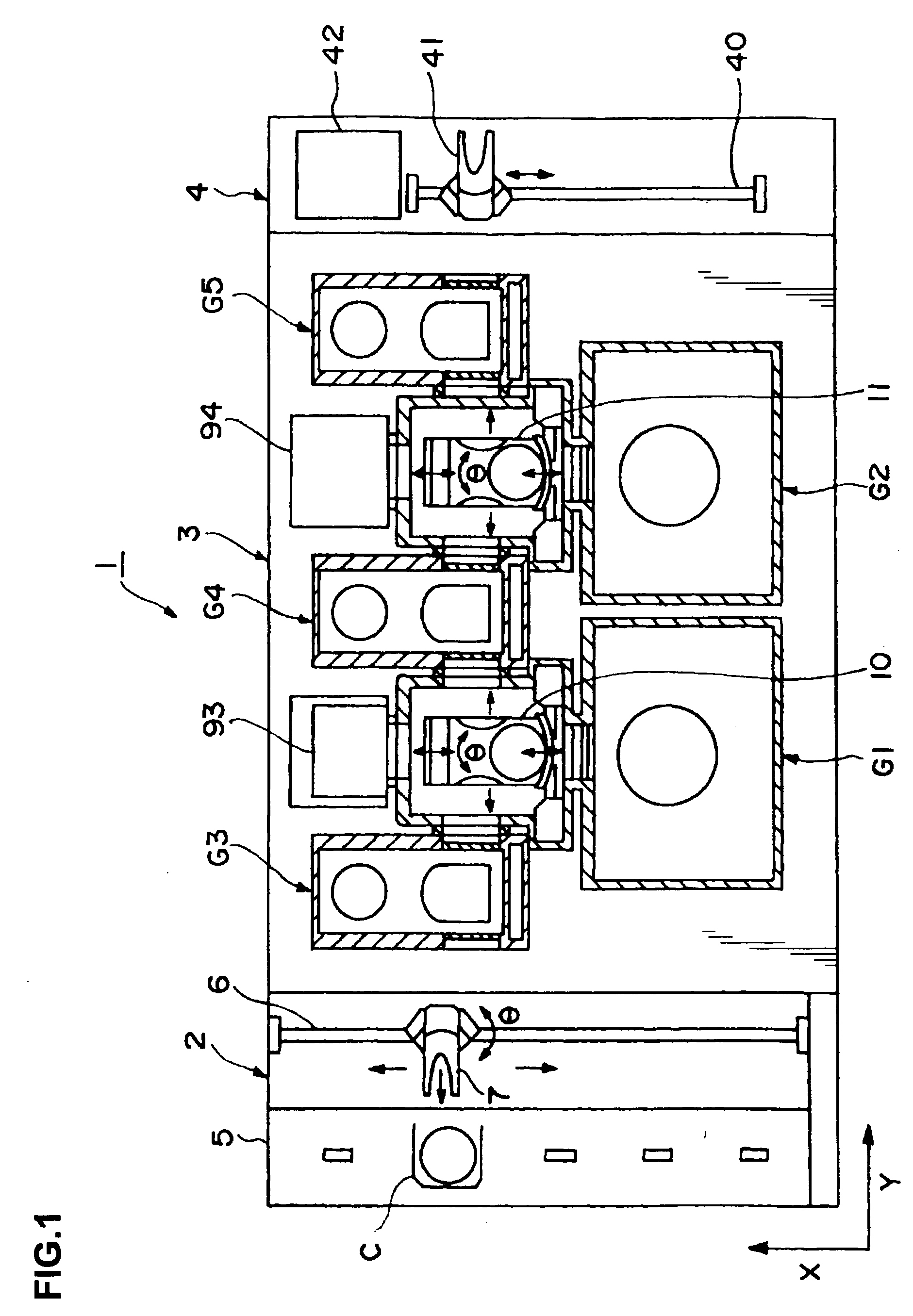
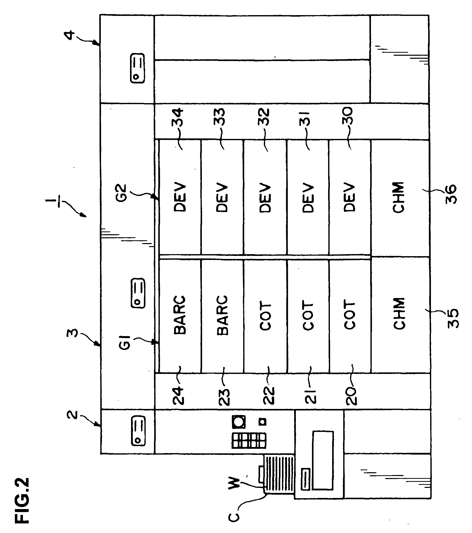
[0035]FIG. 1 is a plan view showing a schematic configuration of the coating and developing apparatus, FIG. 2 is a front view of the coating and developing apparatus in FIG. 1, and FIG. 3 is a rear view of the coating and developing apparatus in FIG. 1.

[0036] The illustrate coating and developing apparatus 1 performs a series of steps of a photolithography process on a wafer being a substrate to be processed in cooperation with an aligner (not shown) to form a predetermined resist pattern on the wafer.

[0037] As shown in FIG. 1, the coating and developing apparatus 1...


PUM


Abstract

In the present invention, in a rinse treatment method of cleaning a substrate after an exposed pattern thereon has been subjected to developing treatment, the following steps are performed such as supplying pure water onto the substrate to clean the substrate with the pure water; supplying a first rinse solution composed of a surfactant with a predetermined concentration onto the substrate to clean the substrate with the first rinse solution; and supplying a second rinse solution composed of a surfactant with a concentration lower than that of the first rinse solution onto the substrate to clean the substrate with the second rinse solution. According to the present invention, in the rinse treatment of the substrate after developing treatment, it is possible to dry the substrate without causing pattern collapse to restrain variation in pattern line width, and to reduce the remaining precipitation-based defects to increase the productivity.

Description

BACKGROUND OF THE INVENTION [0001] 1. Field of the Invention [0002] The present invention relates to a rinse treatment method of performing rinse treatment on a substrate such as a semiconductor wafer after an exposed pattern thereon has been subjected to developing treatment in the photolithography process, a developing treatment method including the rinse treatment method, and a developing apparatus for carrying out the developing treatment method. [0003] 2. Description of the Related Art [0004] In a photolithography process in manufacturing a semiconductor device, for example, a resist coating treatment of applying a resist solution being a coating solution onto, for example, a semiconductor wafer (hereinafter, referred to as a wafer) being a substrate to be processed, to form a resist film, exposure processing of exposing the resist film in a predetermined pattern, heat-processing of accelerating chemical reaction in the resist film after the exposure, developing treatment of de...

Claims


Application Information

Patent Timeline
IPC IPC(8): B08B3/00B08B7/00G03F1/00G03F7/30G03F7/32H01L21/027
CPCG03F7/425H01L21/6715H01L21/67051
Inventor SHIMOAOKI, TAKESHIKITANO, JUNICHI
Owner TOKYO ELECTRON LTD
Learn More