VLIW Acceleration System Using Multi-state Logic

a multi-state logic and acceleration system technology, applied in the field of vliw processors, can solve the problems of hardware emulators that typically require high cost, software simulators that are typically very slow, and simulation of logic designs that require high processing speed and a large number of operations

a multi-state logic and acceleration system technology, applied in the field of vliw processors, can solve the problems of hardware emulators that typically require high cost, software simulators that are typically very slow, and simulation of logic designs that require high processing speed and a large number of operations

US20070074000A1Inactive Publication Date: 2007-03-29LIGA SYST

Image

  • VLIW Acceleration System Using Multi-state Logic
  • VLIW Acceleration System Using Multi-state Logic
  • VLIW Acceleration System Using Multi-state Logic

Examples


Embodiment Construction

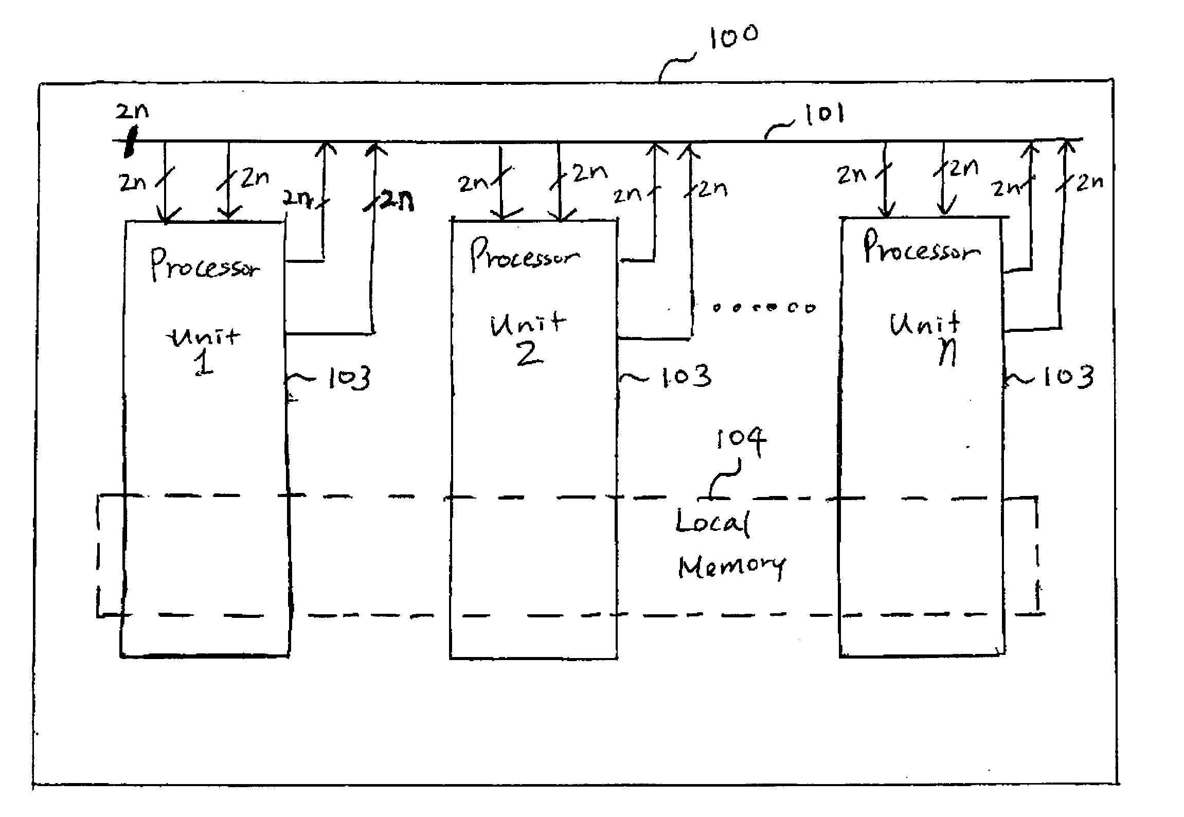
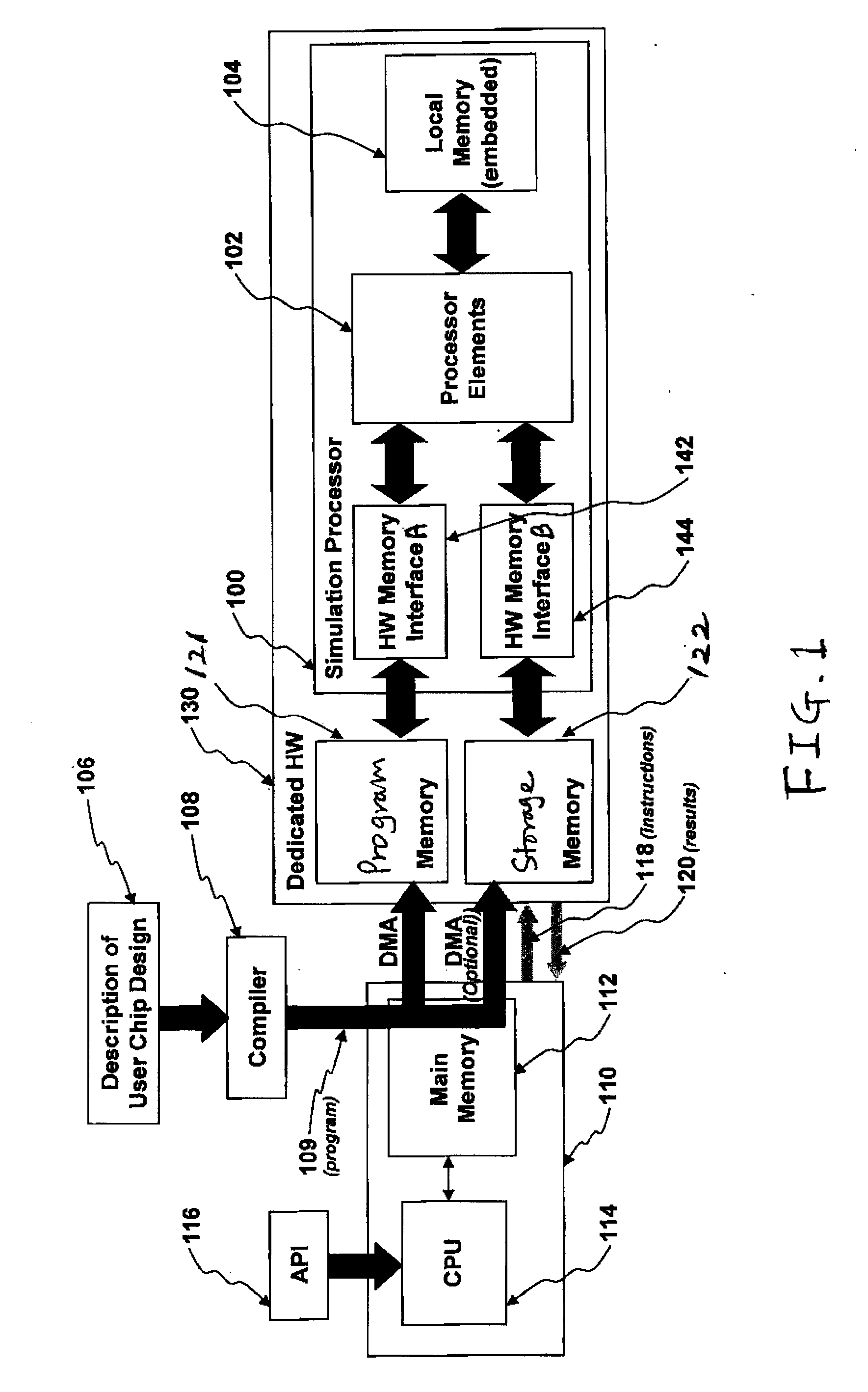
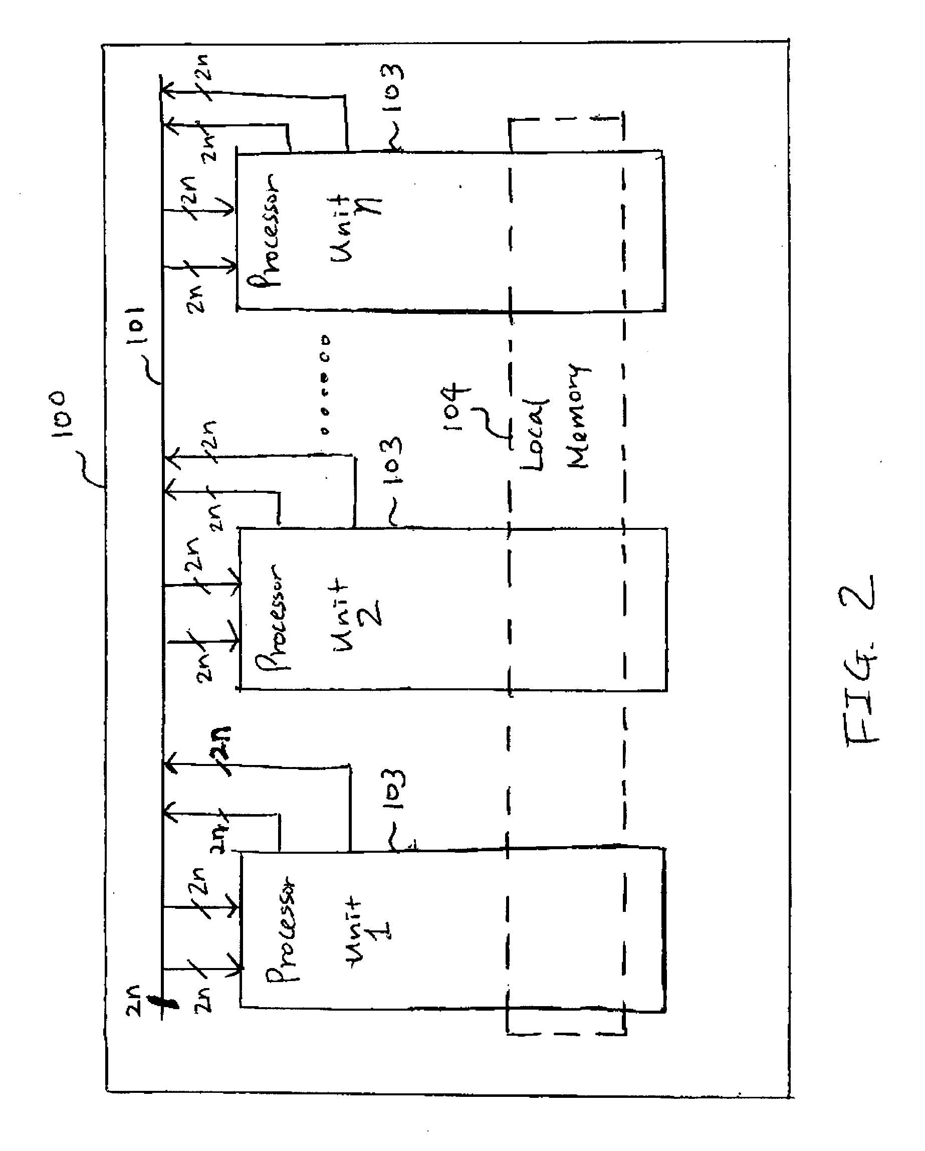
[0027]FIG. 1 is a block diagram illustrating a hardware accelerated logic simulation system according to one embodiment of the present invention. The logic simulation system includes a dedicated hardware (HW) simulator 130, a compiler 108, and an API (Application Programming Interface) 116. The computer 110 includes a CPU 114 and a main memory 112. The API 116 is a software interface by which the host computer 110 controls the simulation processor 100. The dedicated HW simulator 130 includes a program memory 121, a storage memory 122, and a simulation processor 100 that includes processor elements 102, an embedded local memory 104, a hardware (HW) memory interface A 142, and a hardware (HW) memory interface B 144.

[0028] The system shown in FIG. 1 operates as follows. The compiler 108 receives a description 106 of a user chip or logic design, for example, an RTL (Register Transfer Language) description or a netlist description of the logic design. The description 106 typically repre...


PUM


Abstract

A logic simulation processor uses multi-state logic (e.g., in 4-state, signals may take the values 0, 1, X or Z in the simulation of a semiconductor chip design). Typically a reduced number of basic multi-state logic functions are selected for the instruction set of the processor. Logic functions that are not part of the basic set are simulated by constructing them from combinations of the basic logic functions. In this way, the instruction length remains a manageable size but all logic functions that may occur can be simulated. The basic VLIW architecture can be extended to other applications.

Description

CROSS-REFERENCE TO RELATED APPLICATIONS [0001] This application is a continuation-in-part of pending U.S. patent application Ser. No. 11 / 238,505, β€œHardware Acceleration System for Logic Simulation Using Shift Register as Local Cache,” filed Sep. 28, 2005 by Watt and Verheyen; and claims priority under 35 U.S.C. Β§ 119(e) to U.S. Provisional Patent Application Ser. No. 60 / 732,078, β€œVLIW Acceleration System Using Multi-state Logic,” filed Oct. 31, 2005 by Colwill and Verheyen. The subject matter of the foregoing are incorporated herein by reference in their entirety.BACKGROUND OF THE INVENTION [0002] 1. Field of the Invention [0003] The present invention relates generally to VLIW (Very Long Instruction Word) processors, including for example simulation processors that may be used in hardware acceleration systems for logic simulation. More specifically, the present invention relates to the use of VLIW processors that implement multi-state logic. [0004] 2. Description of the Related Art ...

Claims


Application Information

Patent Timeline
29 Mar 2007
Publication
US20070074000A1
IPC
G06F15/00
CPC
G06F17/5022; G06F9/30145; G06F30/33
Inventors
COLWILL, PAUL; VERHEYEN, HENRY T.