
Multicomponent nanorods

Inactive Publication Date: 2007-04-05
NORTHWESTERN UNIV
View PDF11 Cites 63 Cited by
  • Summary
  • Abstract
  • Description
  • Claims
  • Application Information

AI Technical Summary

Benefits of technology

[0016] Yet another aspect of the invention is to provide a lithographic method of producing nanowires comprising impervious metals and having gaps at positions previously containing a sacrificial metal, wherein the lithographic method is compatible with a high-through-put production and with a high level of precision.

Problems solved by technology

There are two general challenges in nanoscience and nanotechnology.
One challenge is to fabricate nanoarchitechtures, such as nano-electrodes, diodes, and resistors, in less than 10 nanometer (nm) resolution.
Although they have many attributes and capabilities, nanolithographic techniques, such as electron beam lithography, dip-pen nanolithography (DPN), focused ion-beam lithography, and nanoimprint lithography, are limited with respect to throughput, materials compatibility, resolution, and / or cost (Gates et al, Chem. Rev., 105, 1171, 2005).
Fabricating such structures is far from routine and often involves low-yielding, imprecise, and difficult-to-control procedures, such as break junction techniques and gap narrowing by electroplating (Reed et al, Science, 278, 252, 1997; Park et al, App Phys Lett, 75, 301, 1999; Li et al, App Phys Lett, 77, 3995, 2000; Xiang et al, Angew Chem Int Ed, 44, 1265, 2005).

Method used


Image

  • Multicomponent nanorods
  • Multicomponent nanorods
  • Multicomponent nanorods

Examples


examples

Synthesis of Multicomponent Metal-Conducting Polymer-Metal Nanorods

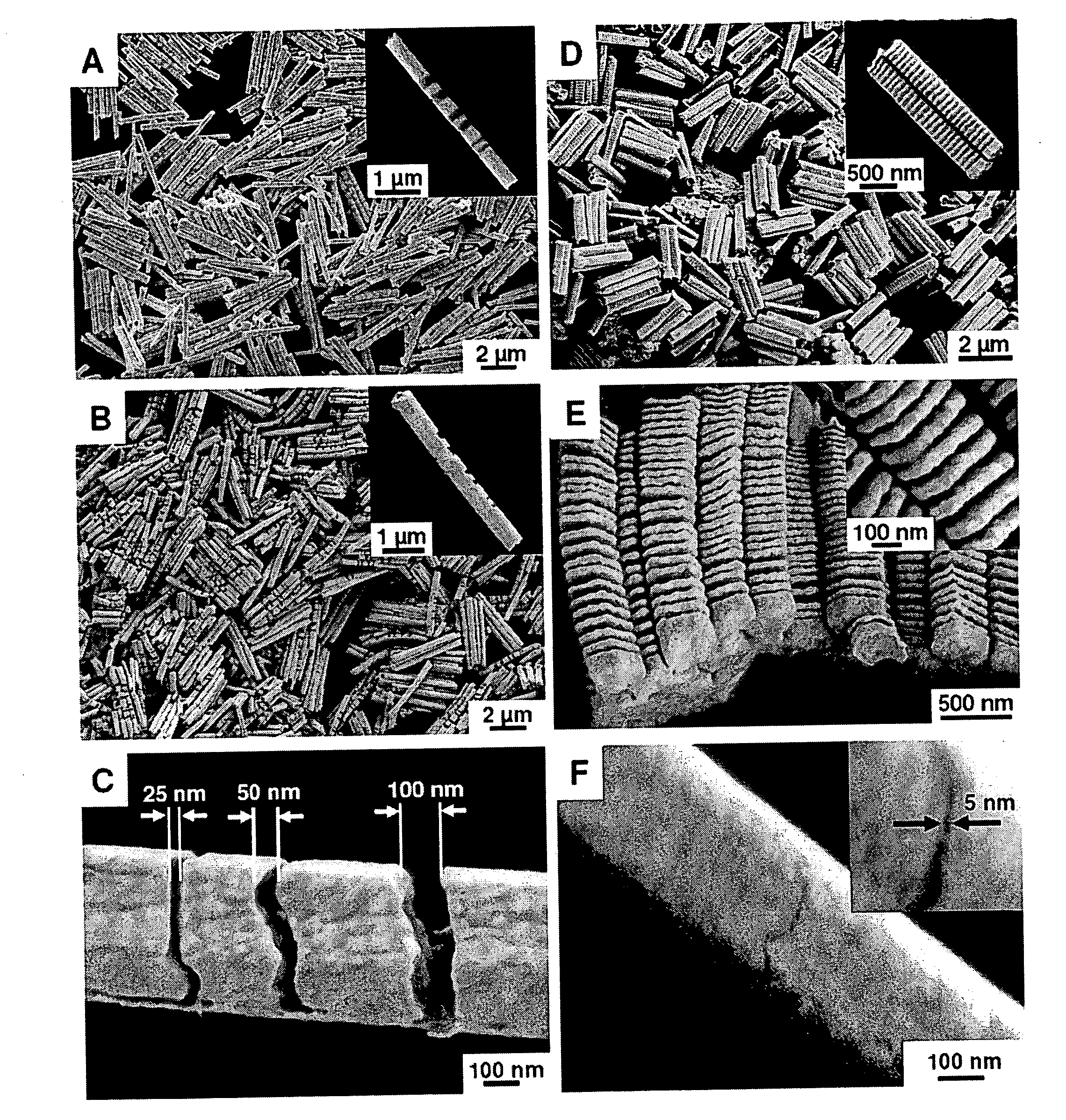
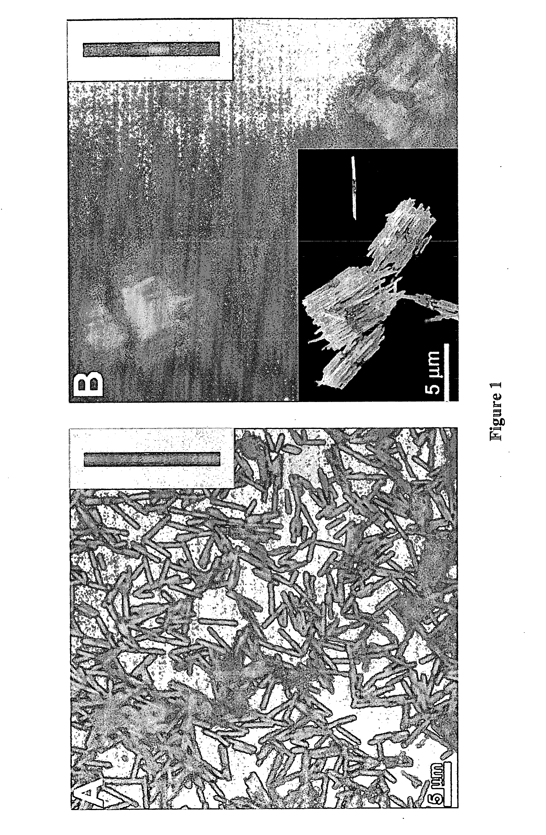
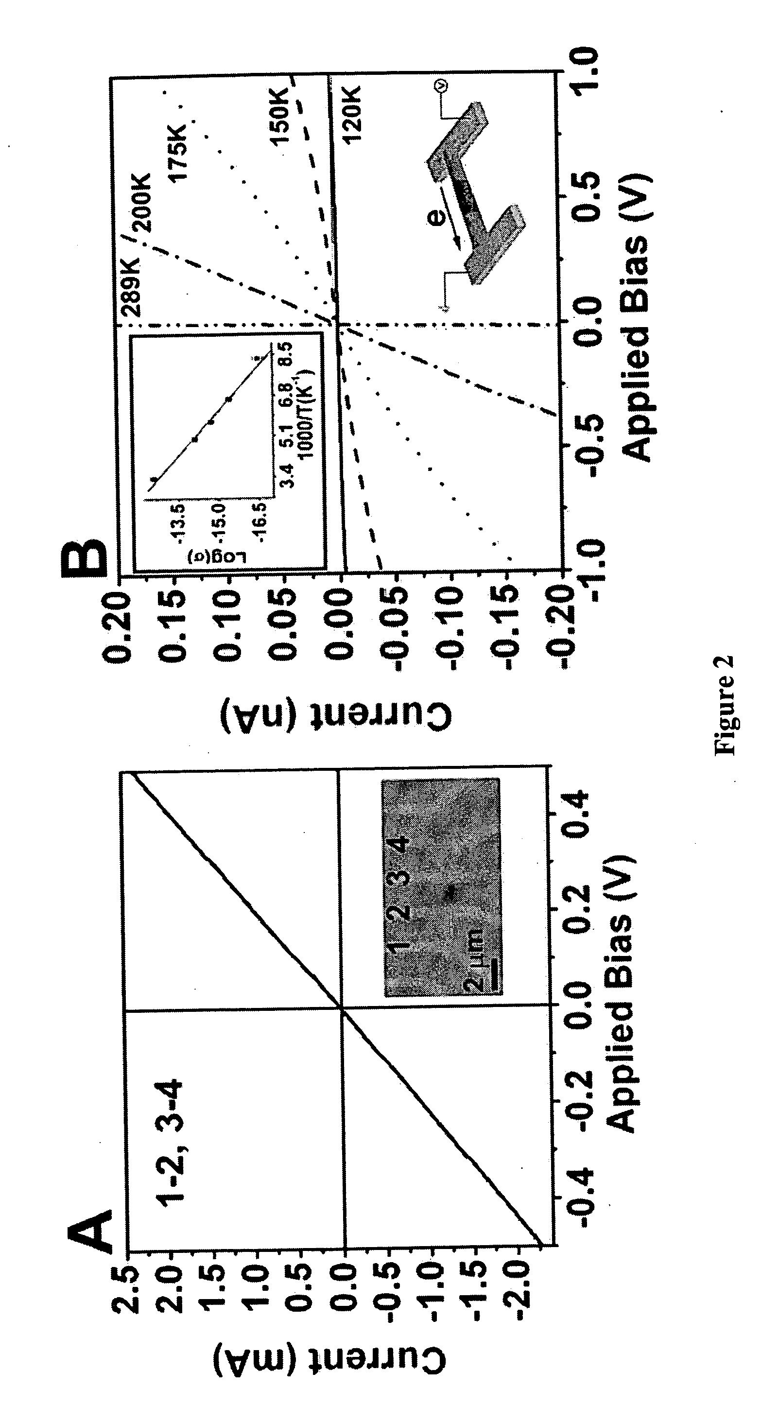
[0075] In a typical experiment, a thin layer of silver (200 nm) was evaporated on one side of an alumina filter (Whatman International Ltd, d=13 mm, pore size—20 nm; the pore diameter in the central region of the filter is substantially larger than the quoted 20 nm) and served as a cathode in a three electrode electrochemical cell after making physical contact with aluminum foil. Platinum wire was used as a counter electrode, and silver / silver chloride (Ag / AgCl) was used as the reference electrode. The nanopores were filled by the electrochemical deposition of Ag (Technic ACR silver RTU solution from Technic, Inc.) at a constant potential, −0.9 V vs. Ag / AgCl, by passing 1.5 C / cm2 for 30 minutes. An Au segment then was electroplated from Orotemp 24 RTU solution (Technic, Inc.) at −0.9 volts (V) vs. Ag / AgCl followed by a conducting polymer segment from various plating solutions at positive potentials. For Ppy segment...


PUM

PropertyMeasurementUnit
Lengthaaaaaaaaaa
Lengthaaaaaaaaaa
Lengthaaaaaaaaaa

Abstract

Multicomponent nanorods having segments with differing electronic and / or chemical properties are disclosed. The nanorods can be tailored with high precision to create controlled gaps within the nanorods or to produce diodes or resistors, based upon the identities of the components-making up the segments of the nanorods. Macrostructural composites of these nanorods also are disclosed.

Description

CROSS-REFERENCE TO RELATED APPLICATIONS [0001] This application is a continuation-in-part of U.S. patent application Ser. No. 11 / 062,983, filed on Feb. 22, 2005, which claims the benefit of U.S. Provisional Application Ser. No. 60 / 546,641, filed Feb. 20, 2004. This application also claims the benefit of U.S. Provisional Application Ser. No. 60 / 584,702, filed Jun. 30, 2004, and U.S. Provisional Application Ser. No. 60 / 661,659, filed Mar. 14, 2005.STATEMENT OF GOVERNMENTAL INTERESTS [0002] This invention was made with government support under Air Force Office of Scientific Research (AFOSR) grants F49620-00-1-0283 and F49620-02-1-0180, National Science Foundation grant EEC-0118025, and Defense Advanced Research Projects Agency (DARPA) grant DAAD-19-03-1-0065 and DARPA Spintronics grant MDA972-03-1-0023. The government has certain rights in this invention.FIELD OF THE INVENTION [0003] The present invention relates to nanoscale compositions for use as nanoresistors and nanodiodes, and to...

Claims


Application Information

Patent Timeline
IPC IPC(8): B32B1/00B05D1/36B05D3/10
CPCB82Y5/00Y10T428/2982B82Y20/00G01N33/531H01C17/06513H01L29/0665H01L29/0673H01L29/068H01L29/861Y10S977/762Y10S977/81Y10S977/849Y10S977/857Y10S977/856Y10T428/2938B82Y10/00
Inventor MIRKIN, CHAD A.QIN, LIDONGPARK, SUNGHOHUANG, LINGCHUNG, SUNG-WOOK
Owner NORTHWESTERN UNIV
Learn More