Method for depositing multi-layer film of mask blank for EUV lithography and method for producing mask blank for EUV lithography

a multi-layer film and mask technology, applied in the field of euv lithography multi-layer film depositing and mask depositing method, can solve the problems of concave defect, inability to mitigate effect, and increased size of concave d

Active Publication Date: 2007-04-05
ASAHI GLASS CO LTD
View PDF9 Cites 28 Cited by
  • Summary
  • Abstract
  • Description
  • Claims
  • Application Information

AI Technical Summary

Benefits of technology

[0057] Accordingly, it is extremely difficult to prepare a substrate having neither a-convex defect nor a concave defect formed thereon. On the other hand, it is comparatively easy to use a conventional wet cleaning method or brush-cleaning to prepare a substrate, which has a relatively rough surface and / or a concave defect formed thereon, and which has no foreign particles existing thereon. In this sense, the methods according to the present invention is effective to fabricate a reflective mask blank for EUV lithography (hereinbelow, referred as “EUV mask blank” in Description), which is free from a convex defect and a concave defect.

Problems solved by technology

However, the defect smoothing method proposed by the non-patent document 5 cannot mitigate the effect caused by a concave defect on a substrate since this method mitigates only the effect caused by a convex defect on a substrate.
On the other hand, the concave defect means a defect formed as a concave portion on (caved in) a substrate surface, such as a pit or a scratch.
However, in this method, a concave defect is increased in size by the same mechanism.
This is one of the disadvantages of this method.
Additionally, this method is a time-consuming method since a film-etching process using a secondary ion source is required after a film deposition process using a primary ion source is carried out.
Ions from the secondary ion source collide with not only a front surface of the substrate but also a shield, causing shield flaking.
The implement of annealing needs to take more time, thus increasing the possibility that foreign particles are generated during this process.

Method used


Image

  • Method for depositing multi-layer film of mask blank for EUV lithography and method for producing mask blank for EUV lithography
  • Method for depositing multi-layer film of mask blank for EUV lithography and method for producing mask blank for EUV lithography
  • Method for depositing multi-layer film of mask blank for EUV lithography and method for producing mask blank for EUV lithography

Examples


example

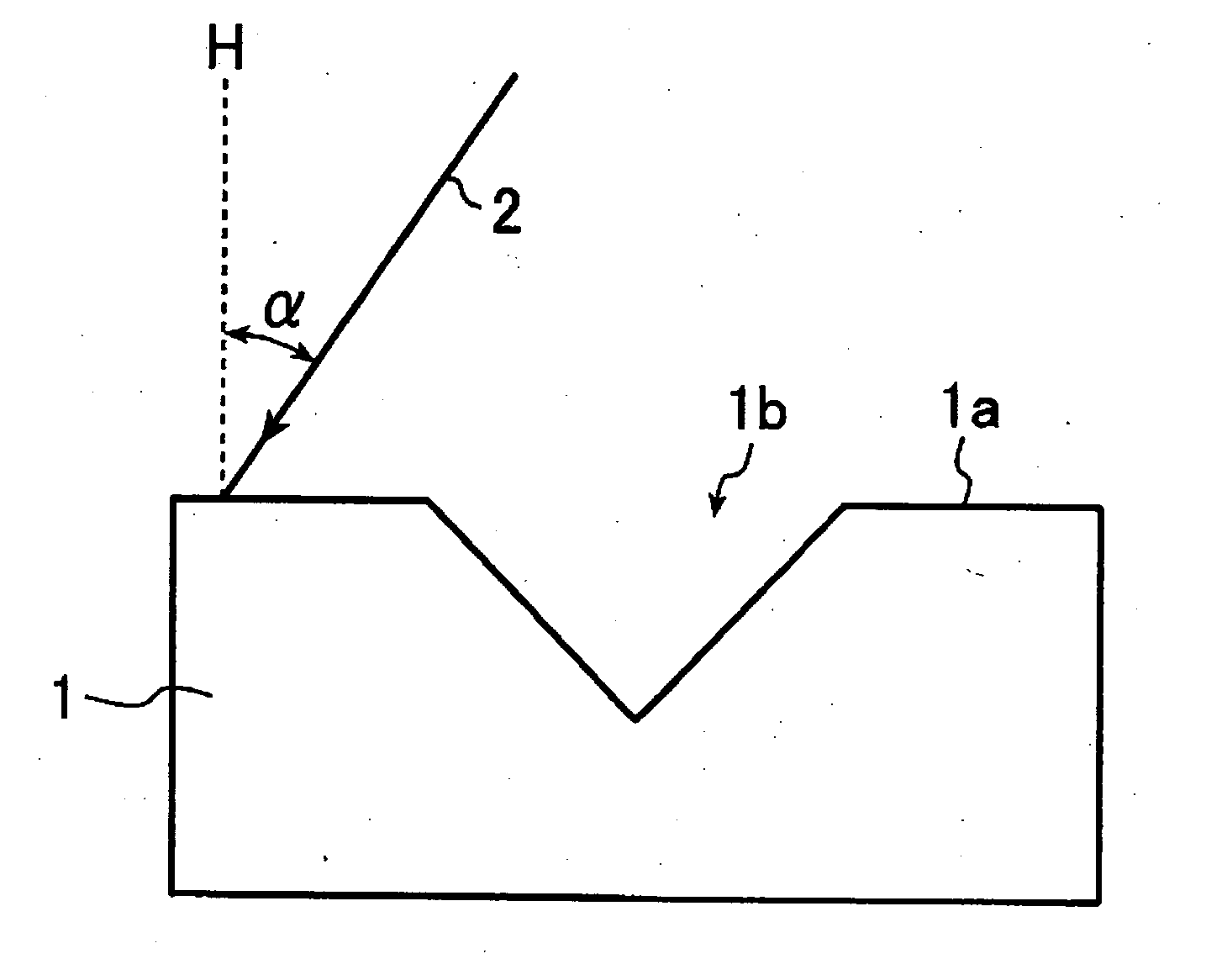
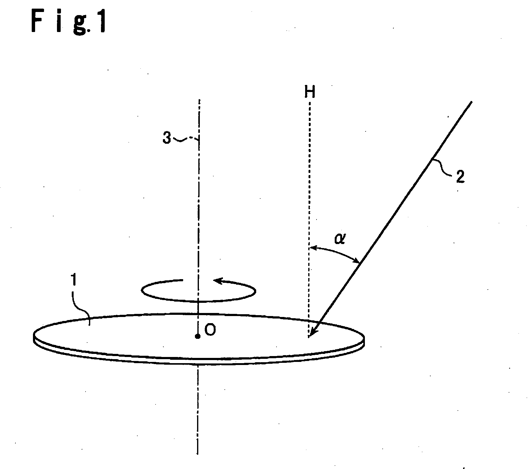
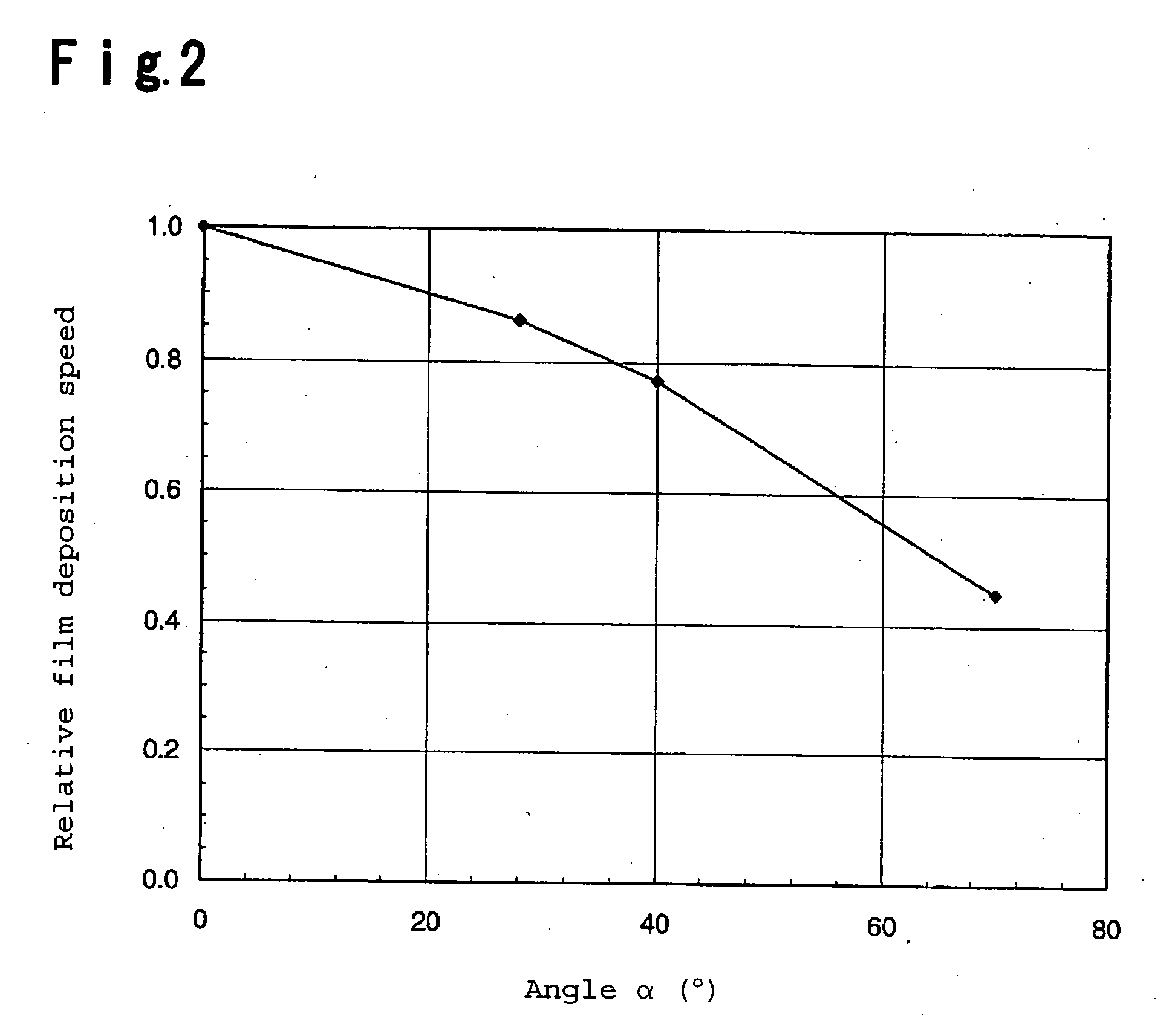
[0173] In this example, an ion beam sputtering method was used to deposit a Mo / Si multilayer reflective coating on substrates having a concave defect formed thereon, and the relationship between an incident angle α of sputtered particles to a normal line of the substrates and the size of a concave defect formed on each of the Mo / Si multilayer reflective coatings were investigated.

[0174] In this example, substrates, each of which had a concave defect (having a diameter of 73 nm in PSL equivalent particle size) formed thereon, were used as substrates for film deposition. The substrate for film deposition were SiO2 / TiO2 glass substrates (having outer dimensions of 6 inch (152.4 mm) square and a thickness of 6.3 mm), which had a coefficient of thermal expansion of 0.2×10⁻⁷ / ° C. and a Young's modulus of 67 GPa.

[0175] The glass substrates were preliminarily polished so as to have a surface roughness of 0.2 nm or below in Rms and a flatness of 100 nm or below, and the above-mentioned con...


PUM

PropertyMeasurementUnit
angleaaaaaaaaaa
widthaaaaaaaaaa
widthaaaaaaaaaa

Abstract

A method for depositing, by ion beam sputtering, a multilayer reflective coating of a reflective mask blank for EUV lithography on a substrate having a concave defect formed thereon, characterized in that the method comprises carrying out ion beam sputtering so that an absolute value of an angle α formed between a normal line of a substrate and sputtered particles landing on the substrate is maintained so as to satisfy the formula of 35°≦α≦80° while rotating the substrate about a central axis thereof.

Description

BACKGROUND OF THE INVENTION [0001] 1. Field of the Invention [0002] The present invention relates to a method for depositing a multilayer film of a mask blank for EUV (Extreme Ultra Violet) lithography by using an ion beam sputtering method, and a method for producing a mask blank for EUV lithography. [0003] 2. Discussion of Background [0004] A reflective coating of a mask blank for EUV lithography (hereinbelow, referred to as “EUV mask blank” in Description) is produced by depositing a multilayer reflective coating, wherein Mo layers and Si layers are alternately laminated on a superpolished substrate. In order to fabricate an EUV mask blank at a reasonable cost, such a multilayer reflective coating is required to satisfy the following characteristics: [0005] Being free of a defect having a size of a certain value or above (a size of 32 nm or above in the case of, e.g., a mask used for fabricating semiconductor devices having a circuit line width of 32 nm) in a quality-assured rang...

Claims


Application Information

Patent Timeline
Patent Type & Authority Applications(United States)
IPC IPC(8): C23C14/32C23C14/00B05D5/06G03F1/00
CPCB82Y10/00B82Y40/00C23C14/046C23C14/225C23C14/46G03F1/24G03F1/68
Inventor IKUTA, YOSHIAKIKRICK, DAVIDMA, HSING CHIGN
Owner ASAHI GLASS CO LTD
Why Eureka
Try Eureka