

Method for applying a low coefficient of friction coating
a technology of friction coating and coating, applied in the direction of coating, chemistry apparatus and processes, plasma techniques, etc., can solve the problems of increased friction and wear, ineffective lubrication, and worsening of condition
- Summary
- Abstract
- Description
- Claims
- Application Information
AI Technical Summary
Benefits of technology
Problems solved by technology
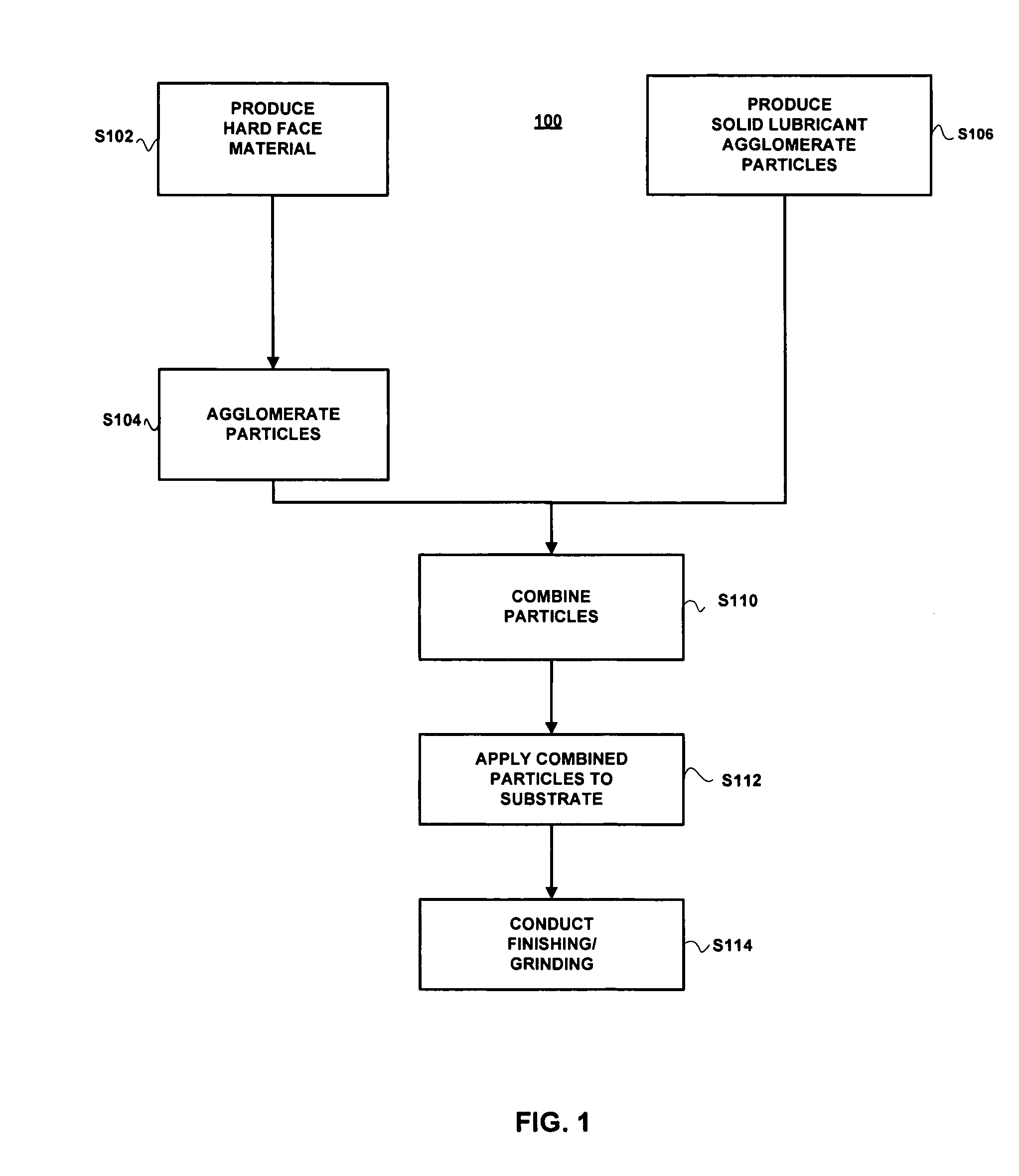
Method used
Image

Examples
Embodiment Construction
[0026] Reference will now be made in detail to the preferred embodiments of the present invention, examples of which are illustrated in the accompanying drawings.
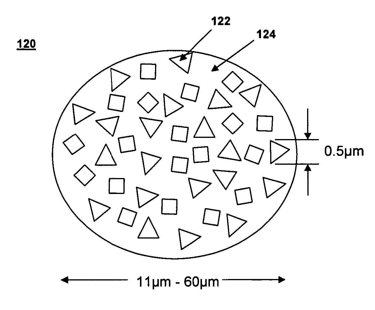
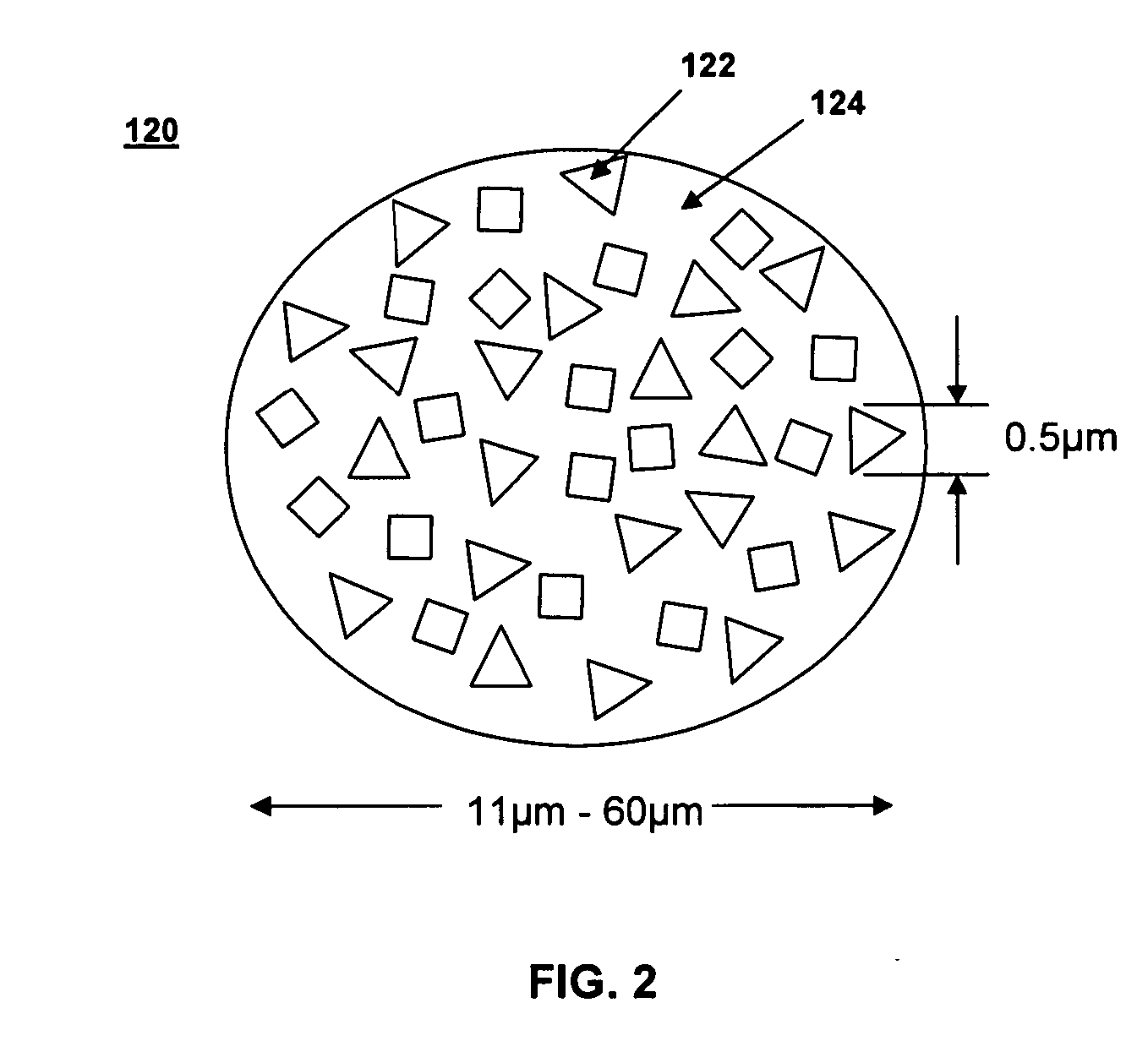
[0027] The invention as defined herein uses two separate thermal spray materials, blended together to achieve a thermal spray coating that combines the benefits achieved with previous thermal spray coatings in terms of wear, abrasion, heat and corrosion with those afforded by solid lubricants. When applied using a thermal spray process in accordance with the invention, the resulting coatings exhibit the properties necessary to provide superior galling, fretting and sliding wear resistance in applications where components requiring lubrication are operated in conditions where the components are at least temporarily void of lubrication or where the lubrication pressure is temporarily compromised. As used herein, thermal spray processes refer to, but are not limited to, high velocity oxygen fuel (HVOF), high velocity liquid f...
PUM
| Property | Measurement | Unit |
|---|---|---|
| particle size | aaaaa | aaaaa |
| particle size | aaaaa | aaaaa |
| particle size | aaaaa | aaaaa |
Abstract
Description
Claims
Application Information