
Position measuring apparatus and positional deviation measuring method

a technology of position measurement and measuring method, which is applied in the direction of instruments, printers, therapy, etc., can solve the problems of affecting the inspection the complexity of sub-resolution assistant features, and the inability to accurately measure the positional deviation of a written mask. achieve the effect of high accuracy of pattern positional deviation of a written mask

Active Publication Date: 2007-05-10
NUFLARE TECH INC
View PDF18 Cites 35 Cited by
  • Summary
  • Abstract
  • Description
  • Claims
  • Application Information

AI Technical Summary

Benefits of technology

[0021] It is an object of the present invention to solve the problems mentioned above and to provide a method and an apparatus of highly accurately measuring a pattern positional deviation of a written mask.
[0025] In accordance with another aspect of the present invention, a positional deviation measuring method includes measuring, in a state of a backside of a substrate being held by a vacuum chuck, a positional deviation of a first pattern that is written after a predicted positional deviation of a pattern written on a frontside of the substrate is corrected in the case of the backside of the substrate being corrected to be flat based on a topography of the backside of the substrate being set on its edge due to minimize the deformation by gravity, and measuring, in a state of the backside of the substrate being supported at three points, a positional deviation of a second pattern that is written after a predicted positional deviation of a pattern written on the frontside of the substrate is corrected in the case of the backside of the substrate being not corrected to be flat.

Problems solved by technology

However, in such exposure technique, it is assumed that sub-resolution assistant features for correcting an optical proximity effect may become complicated.
The sub-resolution assistant features become complicated in proportion as the influence of an aerial image becomes large.
Furthermore, there is also a very big problem concerning the way to inspect sub-resolution assistant features on a mask.
Developing new lithography technique with a light of 157 nm has been given up due to lack of lens material for the optics used for image shrinking and transferring.
Moreover, when fabricating a master EUV mask, it is difficult to predict total deformations of a substrate in the step of forming a reflective film, or in the process of patterning.
It is also very difficult to meet the guidelines of electro-static chucks with precision and accuracy, described in the SEMI standard (SEMI P40-1103), and furthermore to check the chucks being met the specifications.
In the case of employing the method of the electrostatic chuck, etc. in which the area of the surface contacting with a mask is large, there is much possibility of the electric conduction film on the backside being damaged by friction etc. generated at a contact part and such damaged film becoming a particle.
Moreover, if a particle exists on the backside of an EUV mask, there is concern to fail to meet the requirements of image positional accuracy of the pattern because of a local deformation of the EUV mask caused by the mask backside not having a tight contact in and around the particle.
However, to retain and manage the chuck surface to be such clean is very difficult.
Although there is a possibility of the resist partially going around to the side and the backside of the substrate at the time of the application, it is very difficult to remove the residues and adhesive substances, such as resist, on the side or the backside without any influence on the resist of the mask surface.
However, even when the baking process is performed, the resist being a polymer film has a feature of easily damaged and removed.
In this situation, it is easily considered that the resist which unexpectedly goes around to the side or the backside may become a cause of particulate contamination in the pattern writing apparatus because such resist removes or attaches to a contact portion.
Therefore, it becomes difficult to retain the chuck surface in a clean condition.
As a result, since the particles on the electrostatic chuck surface are contacted with the mask backside, keeping the mask backside to be an ideal plane becomes difficult.
Therefore, a problem may arise in the reproducibility when reproducing, by calculation, a state of the substrate backside being corrected to be a desired curved or flat surface.
However, it is very difficult to equip this measuring instrument on the pattern writing apparatus because of structure restrictions of the apparatus.
Accordingly, even if there is a measuring instrument which can be equipped on the pattern writing apparatus in consideration of the structure restrictions, there is concern that resolution of the measuring device may not enough.
Further, even if the pattern writing apparatus can perform writing, a problem occurs in a position measuring apparatus which measures a position of a written pattern.
Therefore, it becomes difficult to retain the chuck surface in a clean state.
However, if the electrostatic chuck is used in the atmosphere, there is a great risk of attracting positive-charged substances in the environment by the static electricity.
Consequently, since particles enter between the electrostatic chuck surface and the mask backside, keeping the mask backside to be an ideal flat surface becomes difficult.
Thus, there is a possibility that highly precise position measurement cannot be obtained.
As mentioned above, there is a problem that when using an electrostatic chuck for holding an EUV mask in the position measuring apparatus, making the electrostatic chuck which fulfills specifications in the guidelines advocated by SEMI is very difficult.
Moreover, even if it becomes possible to use the electrostatic chuck which fulfills the specifications, there is a problem, such as a particle management, in the position measuring apparatus.
In addition, even if it becomes possible to use the electrostatic chuck which fulfills the specifications, there is a problem stated below.
That is, with respect to a pattern written by data correction without using the electrostatic chuck, it is impossible for the position measuring apparatus using the electrostatic chuck to evaluate image placement accuracy of the pattern writing apparatus that has written such pattern.

Method used


Image

  • Position measuring apparatus and positional deviation measuring method
  • Position measuring apparatus and positional deviation measuring method
  • Position measuring apparatus and positional deviation measuring method

Examples


embodiment 1

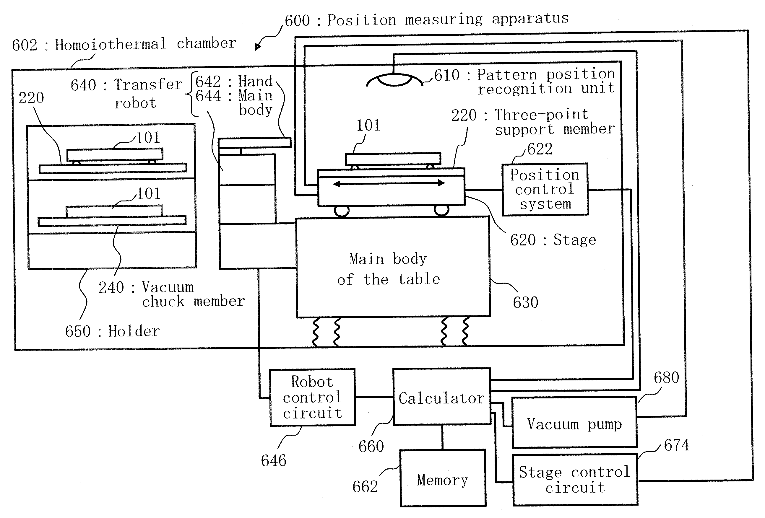
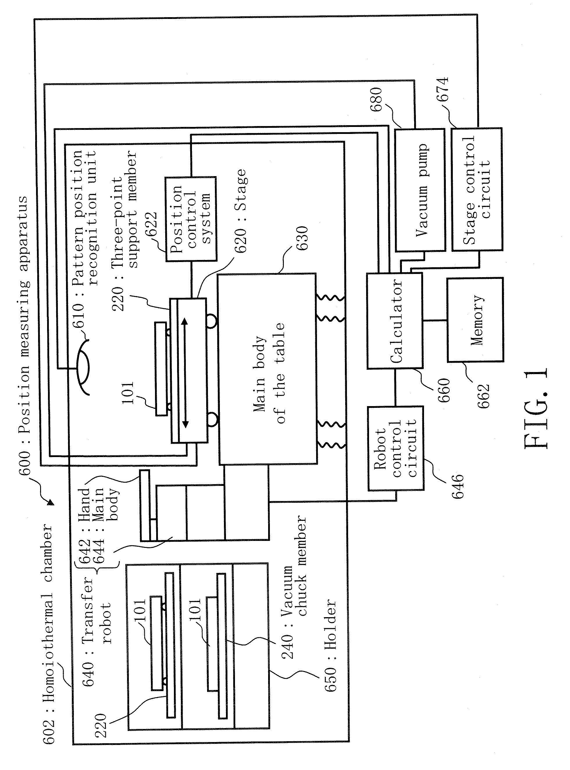
[0051]FIG. 1 is a schematic diagram showing a structure of a position measuring apparatus described in Embodiment 1. As shown in the figure, a position measuring apparatus 600 includes a homoiothermal chamber 602, a pattern position recognition unit 610, a stage 620, a position control system 622, a main body of the table base 630, a transfer robot 640, a holder 650 having storage spaces, a robot control circuit 646, a calculator 660, a memory 662, a vacuum pump 680, and a stage control circuit 674. In the homoiothermal chamber 602, the pattern position recognition unit 610, such as a CCD camera, the stage 620, the position control system 622, the main body of the table base 630, the transfer robot 640, and the holder 650 is stored. The robot control circuit 646, the memory 662, the vacuum pump 680, and the stage control circuit 674 are connected to the calculator 660 to be controlled by it.

[0052] The inside of the homoiothermal chamber 602 is controlled to have a constant temperat...

embodiment 2

[0111]FIG. 17 is a schematic diagram showing a structure of a position measuring apparatus described in Embodiment 2. As shown in the figure, the position measuring apparatus 600 includes the homoiothermal chamber 602, the pattern position recognition unit 610, the stage 620, the position control system 622, main body of the table base 630, the transfer robot 640, the holder 650 having storage spaces, the robot control circuit 646, the calculator 660, the memory 662, the vacuum pump 680, the stage control circuit 674, and a pressure control apparatus 681. Except for the respect that the pressure control system 681 is installed in the primary configuration, namely the exhaust-inlet, of the vacuum pump 680 in FIG. 17, the other respects are the same as those in FIG. 1. The pressure control system 681 includes a pressure sensor 683 and a flow sensor 685.

[0112] The pressure control system 681, being an example of the control system, controls suction force of the vacuum pump 680. For ex...

embodiment 3

[0113]FIG. 18 is a schematic diagram showing a structure of a position measuring apparatus described in Embodiment 3. As shown in the figure, the position measuring apparatus 600 includes the homoiothermal chamber 602, the pattern position recognition unit 610, the stage 620, the position control system 622, the main body of the table base 630, the transfer robot 640, the holder 650 having storage spaces, the robot control circuit 646, the calculator 660, the memory 662, the vacuum pump 680, and the stage control circuit 674. Except for the respect that an identification mark 241 is prepared on each vacuum chuck member 240, the other respects are the same as those in FIG. 1.

[0114] When storing a plurality of holding members, especially a plurality of vacuum chuck members 240 in the holder 650 serving as storage spaces, the identification mark 241 can identify each vacuum chuck member 240.

[0115] Regarding a chuck surface of the electrostatic chuck member used in the exposure appara...


PUM


Abstract

A position measuring apparatus includes a holder having storage spaces in which a three-point support member for supporting a backside of a substrate being a mask at three points, and a vacuum chuck member for holding a backside of a substrate being a mask are prepared, a stage on which one of the three-point support member and the vacuum chuck member prepared in the storage spaces of the holder is mounted, a vacuum pump to hold and chuck the substrate through the vacuum chuck member in a state of being mounted on the stage, and a recognition unit to recognize a position of a pattern written on the substrate supported by the three-point support member mounted on the stage and a position of a pattern written on the substrate held by the vacuum chuck member on the stage.

Description

CROSS-REFERENCE TO RELATED APPLICATION [0001] This application is based upon and claims the benefit of priority from the prior Japanese Patent Application No. 2005-320299 filed on Nov. 4, 2005 in Japan, the entire contents of which are incorporated herein by reference. BACKGROUND OF THE INVENTION [0002] 1. Field of the Invention [0003] The present invention relates to a position measuring apparatus and a positional deviation measuring method and, more particularly, to an apparatus and a method for measuring a pattern positional deviation of EUV (Extreme Ultra Violet) masks written or “drawn” by using variably-shaped electron beams, for example. [0004] 2. Related Art [0005] In recent years, circuit line widths of semiconductors are becoming narrower and narrower with an increase in pattern density. In order to precisely make large scale integrated circuits on a silicon (Si) wafer, exposure technique of transferring an original written on a mask (also called a master or “original” pat...

Claims


Application Information

Patent Timeline
Patent Type & Authority Applications(United States)
IPC IPC(8): G03B27/68
CPCB82Y10/00B82Y40/00G03F1/84G03F7/707G03F7/70708G03F7/70783H01J37/3174H01J2237/2007H01J2237/204H01J2237/2817H01J2237/31776H01L21/6838
Inventor YOSHITAKE, SHUSUKETAMAMUSHI, SHUICHI
Owner NUFLARE TECH INC
Features
  • Generate Ideas
  • Intellectual Property
  • Life Sciences
  • Materials
  • Tech Scout
  • Unparalleled Data Quality
  • Higher Quality Content
  • 60% Fewer Hallucinations
Learn More