

DLC coating, and DLC coating coated tool
a technology of dlc coating and tool, which is applied in the field of dlc coating, can solve the problem of not being suitable as hard coating for cutting tools
- Summary
- Abstract
- Description
- Claims
- Application Information
AI Technical Summary
Benefits of technology
Problems solved by technology
Method used
Image

Examples
Embodiment Construction
[0034] Hereinafter, the embodiment of the present invention will be explained with reference to attached drawings.
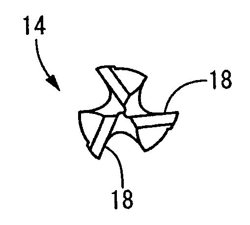
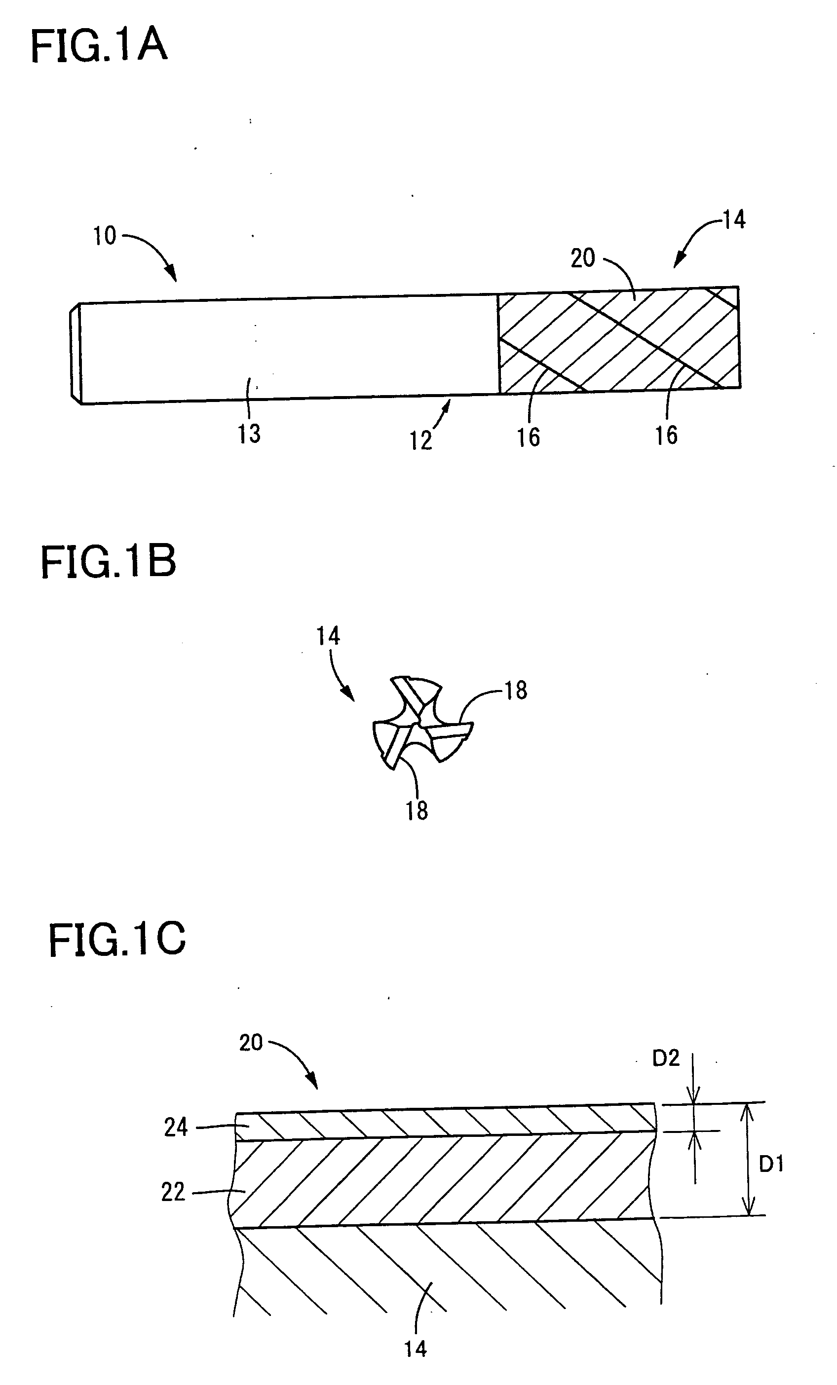
[0035]FIG. 1 shows an end mill 10 which is one example of the DLC coating coated tool according to the present invention, in which FIG. 1A is a schematic front view of the end mill 10 viewed from a direction perpendicular to an axis thereof, and FIG. 1 B is an end view of the end mill 10 viewed from a top end thereof.
[0036] This end mill 10 is a square end mill having three cutting parts, and has a base metal 12 which is made of a cemented carbide and which includes a shank portion 13 and a cutting part 14 formed integrally with each other. On the cutting part 14, a peripheral cutting edge 16 and an end cutting edge 18 are provided as a cutting part, to perform the cutting when the tool is rotated around the axis thereof by a driving source (not shown).
[0037] A surface of the cutting part 14 is coated with a DLC coating 20. The DLC coating 20 is coated on the cutting ...
PUM
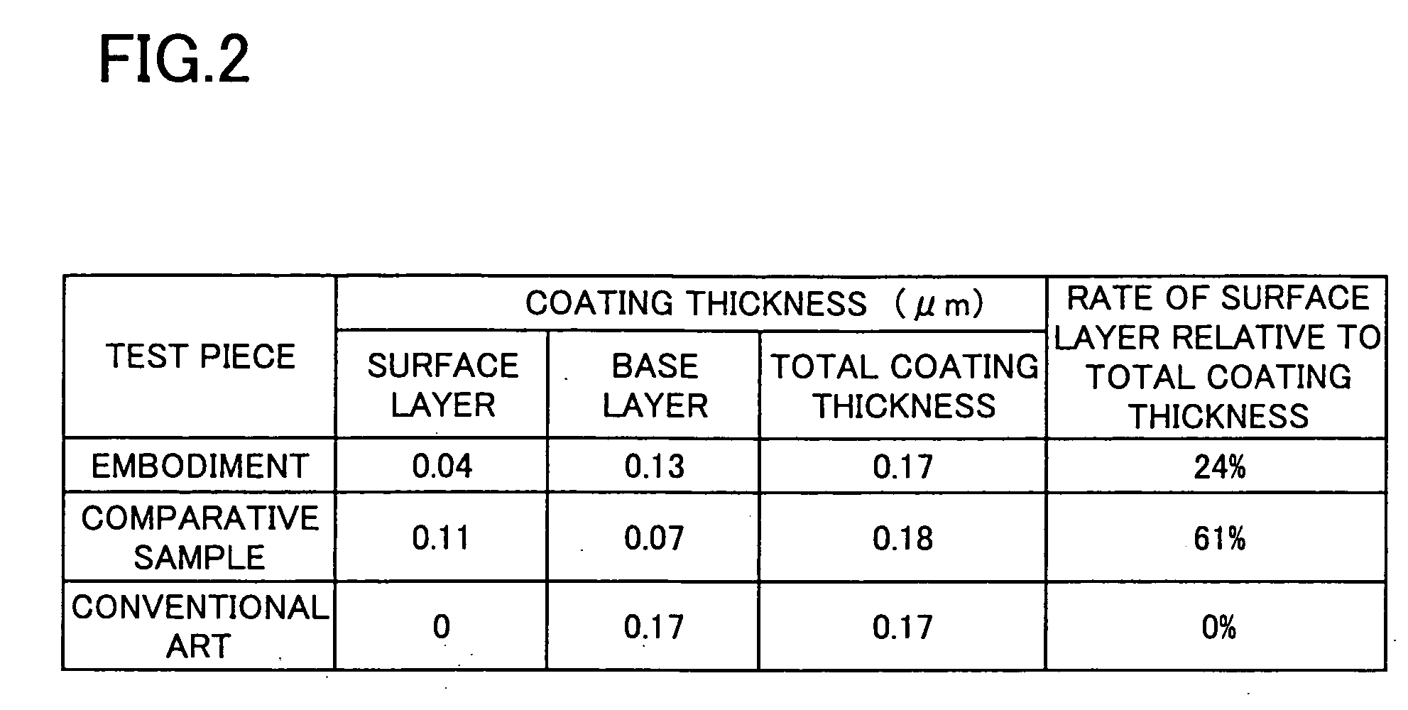
| Property | Measurement | Unit |
|---|---|---|
| thickness | aaaaa | aaaaa |
| thickness | aaaaa | aaaaa |
| total thickness | aaaaa | aaaaa |
Abstract
Description
Claims
Application Information