
Fcc-compliant, movement artifact-free image sensor array with reduced lighting requirement

Inactive Publication Date: 2007-05-24
CAPSO VISION INC
View PDF18 Cites 17 Cited by
  • Summary
  • Abstract
  • Description
  • Claims
  • Application Information

AI Technical Summary

Benefits of technology

[0021] In one embodiment, a group of pixel cells are provided masked from light by opaque material at the outer edge of the pixel cell or sensor array. The data that is read from this group of pixels outside the field of view may be used to compensate for thermal and system noise in the data within the field of view.
[0022] In one embodiment of the present invention takes advantage of the expected leakage current in the sensor array for a capsule camera. Leakage currents exist in all semiconductor devices and constitute a dominant factor in a CMOS image sensor performance. Because the operating temperature of a capsule camera is largely determined by the body temperature, the specification for the leakage current in its CMOS image sensor is orders of magnitude less than that specified for a general-purpose camera. As a result, the timing requirements for pre-charge, exposure and read out of a pixel cell in a capsule camera is relatively more relaxed, as the charge in the pixel cell is expected to leak more gradually than a general-purpose camera. Further, unlike a general-purpose camera, which must meet the externally imposed, varied lighting conditions, the lighting condition under which a capsule camera operates is primarily controlled by the LED of the capsule camera itself. The present invention takes advantage of these and other factors in the design of a capsule-camera, providing a specialized CMOS sensor of improved performance and at a lesser total system cost.
[0023] Prior art CMOS designs, which require the LED be kept uniformly on for both exposure time and the read out time of the sensor array. One embodiment of the present invention shortens this LED on time, thereby providing savings in battery power.
[0024] One embodiment of the present invention provides a new CMOS sensor design suitable for use in a capsule camera or endoscope-specific application saves power by shortening the LED on duration requirement and avoids the “slanting” artifact. In addition, the CMOS sensor allows images to be transmitted within the FCC allocated MISC band for medical applications.

Problems solved by technology

However, they have a number of limitations, present risks to the patient, are invasive and uncomfortable for the patient.
The cost of these procedures restricts their application as routine health-screening tools.
Because of the difficulty traversing a convoluted passage, endoscopes cannot reach the majority of the small intestine and special techniques and precautions, that add cost, are required to reach the entirety of the colon.
Endoscopic risks include the possible perforation of the bodily organs traversed and complications arising from anesthesia.
Moreover, a trade-off must be made between patient pain during the procedure and the health risks and post-procedural down time associated with anesthesia.
Endoscopies are necessarily inpatient services that involve a significant amount of time from clinicians and thus are costly.
The capsule camera allows the GI tract from the esophagus down to the end of the small intestine to be imaged in its entirety, although it is not optimized to detect anomalies in the stomach.
The cost of the procedure is less than for traditional endoscopy due to the decreased use of clinician time and clinic facilities and the absence of anesthesia.
However, these methods all require a physical media conversion during the data transfer process.
One technical challenge for a capsule camera that transmits its images by wireless transmission is the data transmission bandwidth requirement.
However, the data bandwidth available in this band limits image resolution and the frame rate.
In fact, with this data bandwidth, it is difficult to achieve a reasonable image resolution and at a frame rate that is a few frames per second expected of a capsule camera.
Another technical challenge is the avoidance of artifacts.
However, if the subject of the image is moving relative to the camera parallel to the direction of the rows of the sensor array, a line in the field of view perpendicular to that direction would appear to be a slanted line (i.e., the angular orientation of a subject is not correctly preserved).

Method used


Image

  • Fcc-compliant, movement artifact-free image sensor array with reduced lighting requirement
  • Fcc-compliant, movement artifact-free image sensor array with reduced lighting requirement
  • Fcc-compliant, movement artifact-free image sensor array with reduced lighting requirement

Examples


Embodiment Construction

[0037] The Copending Patent Applications disclose a capsule camera that overcomes many deficiencies of the prior art. The present invention provides a capsule camera that is optimized for its special operating environment.

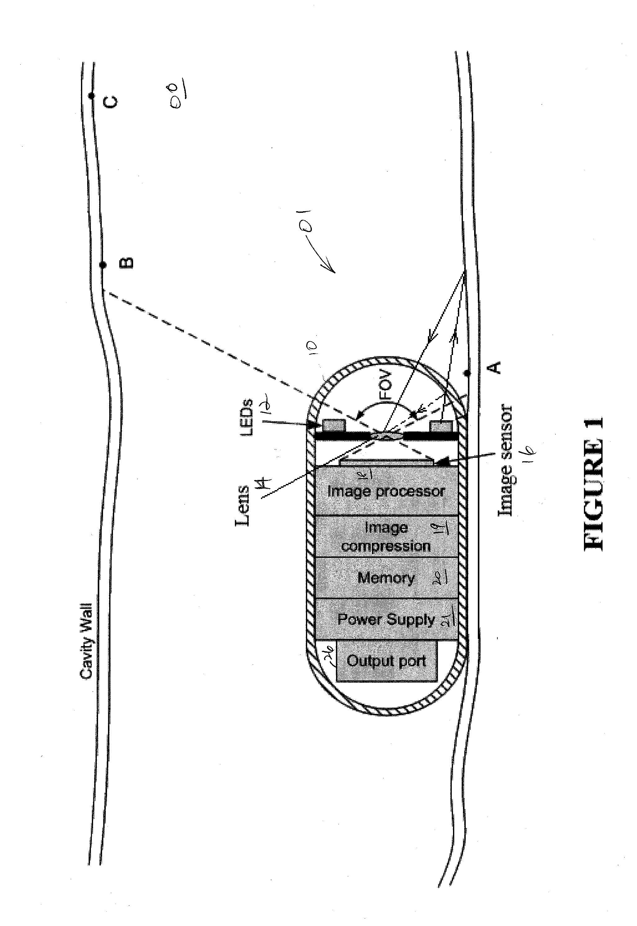
[0038]FIG. 1 shows a swallowable capsule system 01 inside body lumen 00, in accordance with one embodiment of the present invention. Lumen 00 may be, for example, the colon, small intestines, the esophagus, or the stomach. Capsule system 01 is entirely autonomous while inside the body, with all of its elements encapsulated in a capsule housing 10 that provides a moisture barrier, protecting the internal components from bodily fluids. Capsule housing 10 is transparent, so as to allow light from the light-emitting diodes (LEDs) of illuminating system 12 to pass through the wall of capsule housing 10 to the lumen 00 walls, and to allow the scattered light from the lumen 00 walls to be collected and imaged within the capsule. Capsule housing 10 also protects lumen 00 ...


PUM


Abstract

A capsule camera includes a pixel cell array of pixel cells exposed to light from a field of view, an illuminating system that illuminates the field of view, a signal processor receiving and processing data from the pixel cell array, and a control module that causes the pixel cell array to be read out using an improved scanning method. The scanning method includes pre-charging the pixel cells in the pixel cell array, illuminating a field of view of the pixel cells for a predetermined exposure time, and reading out data from the pixel cells only after the illuminating of the field of view is completed. The pre-charging of the pixel cells is carried out over a predetermined time period prior to the field of view being illuminated. The rows of the pixel may be precharged at different times. The time interval between the precharging and the reading out of the pixel cells in each row may be substantially the same. In one instance, the reading out of the pixel cell array is spread out to substantially the time between capturing successive frames of image data. As a result, a transmitter may transmit the processed image data at an average data rate falling substantially within the allowable bandwidth of transmission under the FCC MISC band. In one instance, each row of pixel cells is exposed for the entire duration the illumination system is turned on. A group of pixel cells may be provided outside of the field of view (e.g., at the outer edge of the pixel cell or sensor array. The data that is read from this group of pixels outside the field of view may be used to compensate for thermal and system noise in the data within the field of view.

Description

CROSS-REFERENCES TO RELATED APPLICATIONS [0001] The present invention related, and claims priority, to (1) U.S. Provisional Patent Application, entitled “InVivo Autonomous Sensor with On-Board Data Storage,” Ser. No. 60 / 739,162, filed on Nov. 23, 2005; (2) U.S. Provisional Patent Application, entitled “InVivo Autonomous Sensor with Panoramic Camera,” Ser. No. 60 / 760,079, filed on Jan. 18, 2006; and (3) U.S. Provisional Patent Application, entitled “InVivo Autonomous Sensor with On-Board Data Storage,” Ser. No. 60 / 760,794, filed on Jan. 19, 2006. These U.S. Provisional Patent Applications (1)-(3) (collectively, the “Provisional Patent Applications”) are hereby incorporated by reference in their entireties. The present application is also related to (1) U.S. Patent Application, entitled “In Vivo Autonomous Camera with On-Board Data Storage or Digital Wireless Transmission In Regulatory Approved Band,” Ser. No. 11 / 533,304, and filed on Sep. 19, 2006; and (2) U.S. Patent Application, en...

Claims


Application Information

Patent Timeline
IPC IPC(8): H04N5/335A61B1/04H04N5/341
CPCA61B1/041H04N5/2251H04N5/23248H04N5/2354H04N5/3532H04N2005/2255H04N23/555H04N23/60H04N23/68H04N23/74H04N25/531
Inventor WANG, KANG-HUAI
Owner CAPSO VISION INC
Features
  • Generate Ideas
  • Intellectual Property
  • Life Sciences
  • Materials
  • Tech Scout
  • Unparalleled Data Quality
  • Higher Quality Content
  • 60% Fewer Hallucinations
Learn More