Remote plasma pre-clean with low hydrogen pressure

Active Publication Date: 2007-05-24
APPLIED MATERIALS INC
View PDF44 Cites 35 Cited by
  • Summary
  • Abstract
  • Description
  • Claims
  • Application Information

AI Technical Summary

Benefits of technology

[0008] One aspect of the invention includes plasma dry cleaning of a substrate, particularly a low-k dielectric containing significant carbon and having a high porosity, with a plasma of hydrogen radicals produced by a re

Problems solved by technology

The polymeric coating 18 and the ashing residues 22 interfere with the bonding of the barrier layer to the dielectric layer 14 so that the barrier layer and copper via structure may delaminate during fabrication or during operation, resulting in a substantial reliability problem.
However, low-k dielectric layers tend to be relatively soft.
Therefore, a sputter etch tends to deleteriously etch and degrade the low-k dielectric layer.
However

Method used


Image

  • Remote plasma pre-clean with low hydrogen pressure
  • Remote plasma pre-clean with low hydrogen pressure
  • Remote plasma pre-clean with low hydrogen pressure

Examples


Example

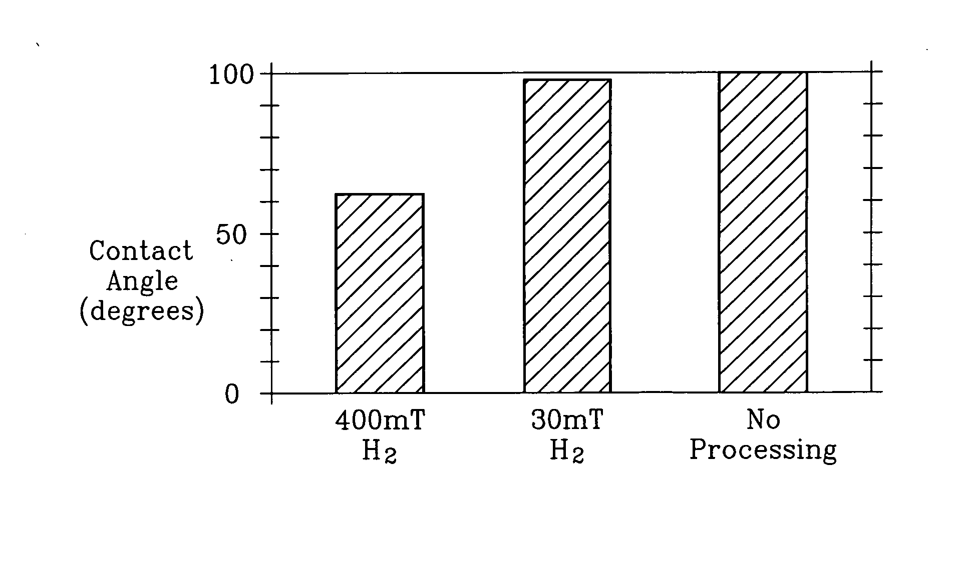
[0020] It has been observed that a very low pressure or even partial pressure of hydrogen from a remote plasma source with a substantial absence of oxygen or water provides acceptable and even superior etch rate and significantly reduces the increase of dielectric constant during dry cleaning.

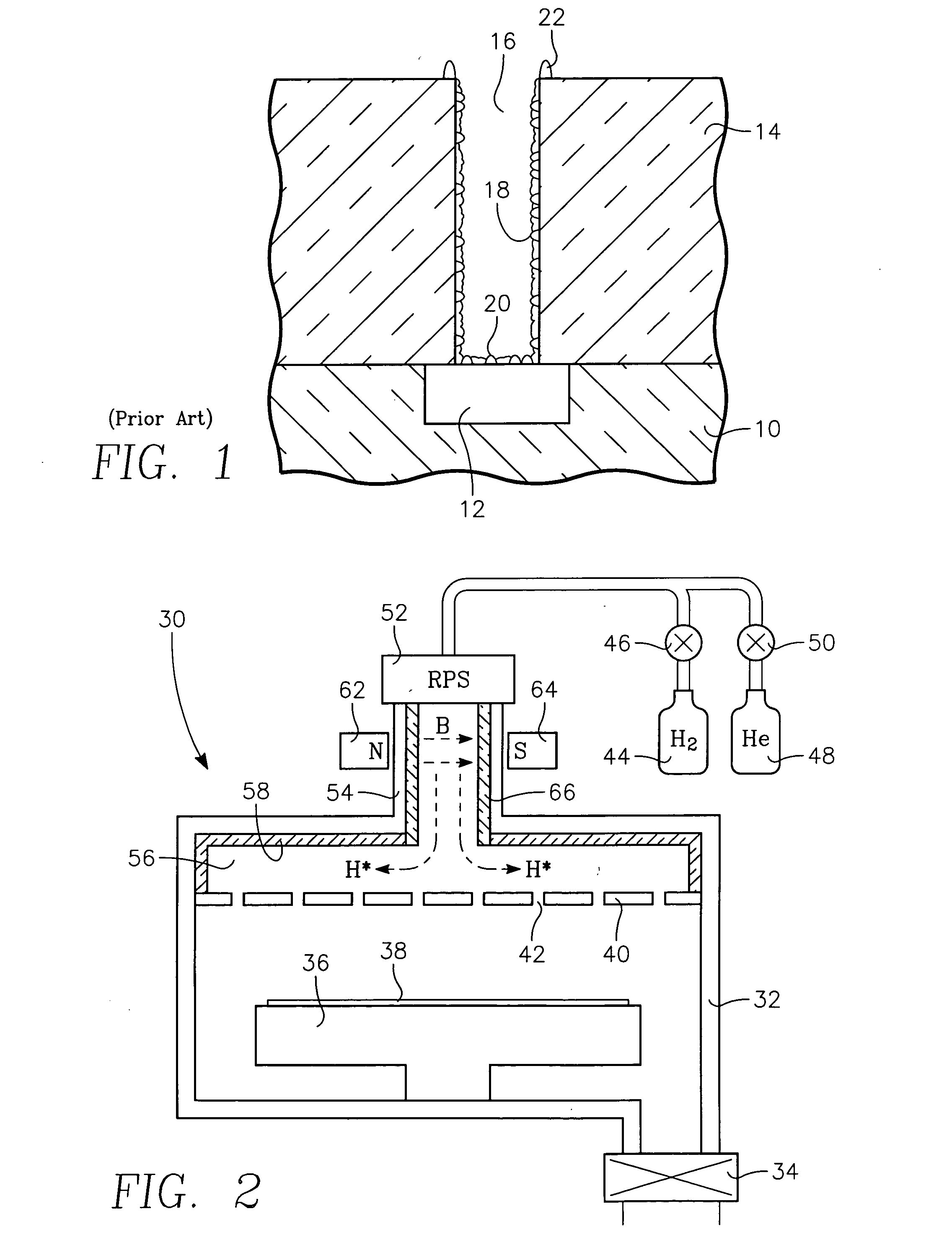
[0021] A remote plasma cleaning chamber 10 illustrated in the cross-sectional view of FIG. 1 includes a vacuum chamber 32 pumped by a vacuum pump system 34. A pedestal 36 within the chamber 36 supports a wafer 38 to be cleaned in opposition to a gas showerhead 40 supplying a process gas through a large number of apertures 42. The pedestal 36 includes a heater to raise the temperature of the wafer 38 to a desired etching temperature. The process gas according to one aspect of the invention is either pure hydrogen gas (H2), which is supplied from a hydrogen gas source 44 through a mass flow controller 46, or a combination of hydrogen and helium (He), which is supplied from a helium gas source 48...


PUM


Abstract

A plasma cleaning method particularly useful for removing photoresist and oxide residue from a porous low-k dielectric with a high carbon content prior to sputter deposition. A remote plasma source produces a plasma primarily of hydrogen radicals. The hydrogen pressure may be kept relatively low, for example, at 30 milliTorr. Optionally, helium may be added to the processing gas with the hydrogen partial pressure held below 150 milliTorr. Superior results are obtained with 70% helium in 400 milliTorr of hydrogen and helium. Preferably, an ion filter, such as a magnetic filter, removes hydrogen and other ions from the output of the remote plasma source and a supply tube from the remote plasma source includes a removable dielectric liner in combination with dielectric showerhead and manifold liner.

Description

RELATED APPLICATION [0001] This application is a continuation in part of Ser. No. 11 / 284,775, filed Nov. 22, 2005 and incorporated herein by reference.FIELD OF THE INVENTION [0002] The invention relates generally to plasma cleaning in the process of fabricating integrated circuits. In particular, the invention relates to plasma cleaning performed between patterned etching of a dielectric layer and deposition. BACKGROUND ART [0003] Advanced integrated circuits, such as those contemplated for the 45 nm node, will require the use of extra low-k dielectric (electrically insulating) materials for the interlevel dielectric layer interconnecting two levels of wiring. Low-k materials having a dielectric constant of somewhat less than 3.9 (the value for silicon dioxide) have already entered commercial production. However, even lower dielectric constants, for example, below 2.5, will be required in the future. An example of this material is Black Diamondâ„¢ II (BDII) dielectric dielectric comme...

Claims


Application Information

Patent Timeline
IPC IPC(8): B08B3/00H01L21/302
CPCG03F7/427H01J37/32357H01J37/32422H01J37/3266H01L21/02063H01L21/02068H01L21/67028H01L21/67069H01L21/76814
Inventor FU, XINYUFORSTER, JOHNYU, JICKBHATNAGAR, AJAYGOPALRAJA, PRABURAM
Owner APPLIED MATERIALS INC
Why Eureka
Try Eureka