Antiglare antireflective film, polarizing plate and liquid crystal display

a technology of anti-glare film and liquid crystal display, which is applied in the direction of optics, coatings, instruments, etc., can solve the problems of reducing the resolution of images, relieve the glare problem, and reduce the distance from viewers to the display, so as to improve image blur, improve the effect of anti-glare quality and high productivity

Active Publication Date: 2007-05-31
FUJIFILM CORP
View PDF2 Cites 107 Cited by
  • Summary
  • Abstract
  • Description
  • Claims
  • Application Information

AI Technical Summary

Benefits of technology

[0556] Although the present film and polarizing plate can be applied to any of displays including those described below, the application of the present film and polarizing plate to the foregoing display in particular, which has high brightness, a high contrast ratio and a wide viewing angle, can provide reinforced and highly modulated black images on the screen and therefore shows white blue even by slight intrusion of extraneous light, can fully achieve the effects of the invention because the present film and polarizing plate can control appropriately the scattering and reflection of extraneous light.
[0557] A plasma display panel (PDP) is generally made up of a gas, glass substrates, electrodes, an electrode lead material, a thick-film print material and fluorescent substances. The glass substrates are a front glass substrate and a rear glass substrate. Each glass substrate is provided with an electrode and an insulation layer. The rear glass substrate is further provided with fluorescent-substance layers. These two glass substrates are assembled, and a gas is sealed into a space between them.
[0558] Plasma display panels are already commercially available. Descriptions thereof can be found in JP-A-5-205643 and JP-A-9-306366.
[0559] In some cases, a front plate is placed in front of a plasma display panel. It is appropriate that the front plate be strong enough to protect the plasma display panel. The front plate can be used in a state that there is a clearance between the front plate and the plasma display panel, or in a state that the front plate is bonded directly to the plasma display panel itself.
[0560] In image displays including a plasma display panel, an optical filter can be stacked directly on the display surface. When a front plate is provided in front of the display, the optical filter may be stacked on either the front side (outside) or rear side (display side) of the front plate. <Touch Panel>
[0561] The present film can be applied to touch panels as disclosed in JP-A-5-127822 and JP-A-2002-48913. <Organic Electroluminescent Device>

Problems solved by technology

In such applications, the glare problem is relieved because the pixel size becomes larger as far as the definition is the same, and besides, the distances from viewers to displays become greater.
Although the antiglare films having high internal scattering quality, which have been widely used as antiglare measures, have been used in those applications also, the high internal scattering quality causes a problem of lowering the resolutions of images (referred to as image blur), so the use of antiglare films is not always suitable for those applications.
However, certain of those attempts (JP-A-2002-23870 and JP-A-2003-107205) are insufficient for performance improvements in all directions, and raise issues of productivity and cost.

Method used


Image

  • Antiglare antireflective film, polarizing plate and liquid crystal display
  • Antiglare antireflective film, polarizing plate and liquid crystal display
  • Antiglare antireflective film, polarizing plate and liquid crystal display

Examples


example 1

(1) Coating of Antiglare Layer

[0656] A roll of 80-μm-thick triacetyl cellulose film (TAC-TD80U, produced by Fuji Photo Film Co., Ltd.) was wound off, and thereon the coating solution A for an antiglare layer was coated in accordance with the die coating method specified by the apparatus configuration as shown in FIGS. 5 to 8 and the coating conditions mentioned below. After the solvent was dried, the layer coated was further cured under a nitrogen-purged atmosphere by irradiation with ultraviolet rays from a 160 W / cm air-cooled metallic halide lamp (made by Eyegraphics Co., Ltd.) at an exposure of 90 mJ / cm2, thereby forming a 6-μm-thick antiglare layer having an antiglare quality, and then wound.

[0657] Basic conditions: The slot die 13 having an upstream-side lip land length IUP of 0.5 mm, a downstream-side lip land length ILO of 50 μm, a slot mouth 16a length of 150 μm in the web traveling direction and a slot 16 length of 50 mm was used. The gap between the upstream-side lip la...

example 2

(Making of Polarizing Plate)

[0684] An 80-μm-thick triacetyl cellulose film (TAC-TD80U, made by Fuji Photo Film Cp., Ltd.) having undergone 2-minute immersion in an aqueous solution containing 1.5 mol / L of NaOH at 55° C., neutralization and washing with water in sequence and each of the antiglare antireflective films made in Example 1 (Example 1F to Example 5F and Comparative Example 1F to Comparative Example 6F, which had already undergone the saponification treatment) were bonded to both sides of a polarizer formed by making polyvinyl alcohol adsorb iodine and stretching the resultant polyvinyl alcohol, and gave protection to the polarizer. The thus made polarizing plates were designated as Example 1P to Example 5P and Comparative Example 1P to Comparative Example 6P, respectively. Incidentally, each antiglare antireflective film was placed so that the triacetyl cellulose film thereof was bonded to the polarizer.

[0685] In addition, a polarizing plate was made using the foregoing...

example 3

(Evaluation of Polarizing Plate)

[0686] Part of the viewing-side polarizing plate mounted in a liquid crystal TV (LC20S4, made by Sharp Corporation) was peeled away, and in place of this plate each of the polarizing plates Example 1P to Example 5P and Comparative Example 1P to Comparative Example 6P made in Example 2 was stacked via an adhesive. Incidentally, each antiglare antireflective film was placed so as to form the viewing-side topmost surface of the liquid crystal TV. Evaluations of the following items were made on the displays thus obtained. Evaluation results are shown in Table 3.

(1) Image Blur

[0687] A sequence of 25 complex Min-cho type characters “” of ten-point size was displayed in ten lines on a white background of each of the LCD panels. These displayed characters were compared with those displayed on the LCD panel using the polarizing plate having no antiglare quality. The extent of blur of the character outline (image blur) was evaluated in accordance with the ...


PUM

PropertyMeasurementUnit
tilt angleaaaaaaaaaa
transparentaaaaaaaaaa
tilt angleaaaaaaaaaa

Abstract

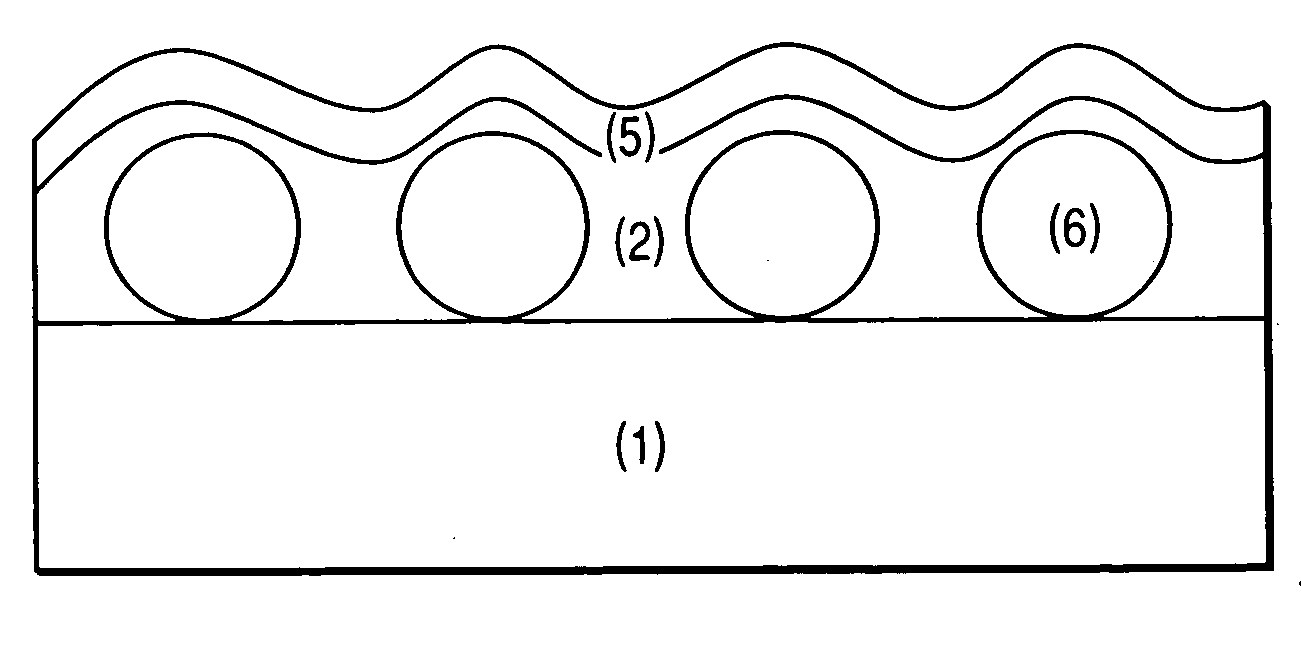
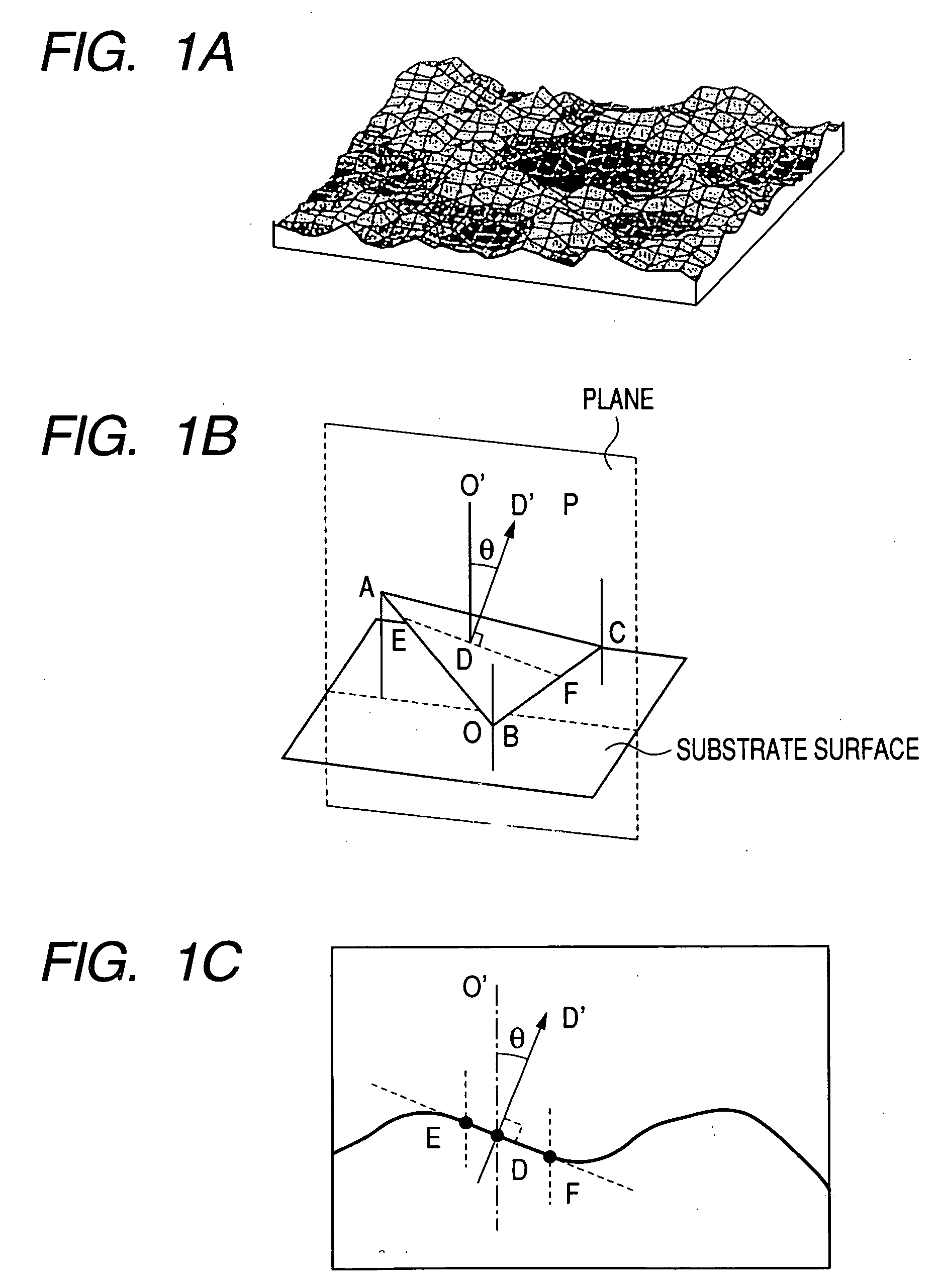
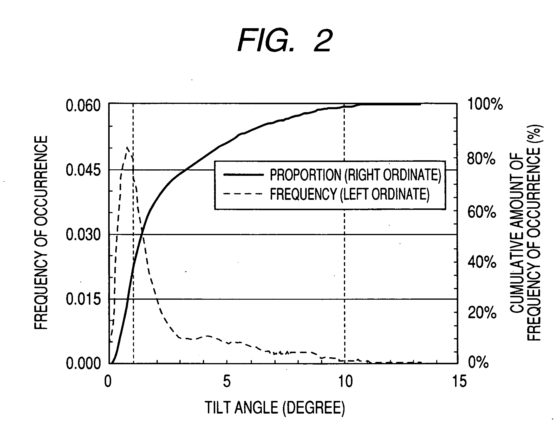
An antiglare antireflective film is provided and includes: a transparent substrate; and at least one layer. The antiglare antireflective film having a surface having asperities in which: 15% to 70% of the total asperities are asperities, each having a tilt angle of 1° or below, which a line normal to each asperity profile form with a line normal to the transparent substrate; and at most 3% of the total asperities are asperities, each having the tilt angle of 10° or above.

Description

BACKGROUND OF THE INVENTION [0001] 1. Field of the Invention [0002] The present invention relates to an antiglare antireflective film, and to a polarizing plate and a liquid crystal display each using such a film. [0003] 2. Description of Related Art [0004] Antiglare films can be broadly divided into two groups: antiglare films having a surface scattering quality in a substantial sense and those having both surface scattering and internal scattering qualities. In a display, such as CRT, a plasma display panel (PDP), an electroluminescent display (ELD) and a liquid crystal display (LCD), an antiglare film is generally placed at the topmost surface of the display for the purpose of avoiding formation of reflected images by reflection of extraneous light. [0005] With the recent trend moving notably toward higher-definition displays, the arts of antiglare films having internal scattering quality higher than usual in addition to surface scattering quality are disclosed in Japanese Patent...

Claims


Application Information

Patent Timeline
Patent Type & Authority Applications(United States)
IPC IPC(8): G02B27/00
CPCG02B1/11G02B5/0221G02B5/0242G02B5/0268G02B5/0278G02B5/0294G02B5/3033
Inventor WATANABE, JUNKATO, SHINYA
Owner FUJIFILM CORP
Why Eureka
Try Eureka