Resist protective film material and pattern formation method

a protective film and pattern formation technology, applied in the direction of photosensitive materials, photomechanical equipment, instruments, etc., can solve the problems of not being suited to the preparation of antireflective films, the essential limit of resolution of light exposure currently on widespread use in the art, and the use of fluorocarbons now becomes a problem. , to achieve the effect of excellent process adaptability

Inactive Publication Date: 2007-05-31
SHIN ETSU CHEM IND CO LTD
View PDF20 Cites 42 Cited by
  • Summary
  • Abstract
  • Description
  • Claims
  • Application Information

AI Technical Summary

Problems solved by technology

However, light exposure which is currently on widespread use in the art is approaching the essential limit of resolution determined by the wavelength of a light source.
As is well-known in the art, use of fluorocarbon now becomes a problem from the standpoint of environmental protection.
In addition, the above compounds do not have a uniform film forming property so that they are not suited for the preparation of antireflective films.
Accordingly, there are many practical disadvantages including a need to add a unit for removing an antireflective film to the existing system and an increase in the cost of fluorocarbon solvents.
However, the water-soluble protective films are dissolved in water during exposure so that they cannot be used in the immersion lithography.

Method used


Image

  • Resist protective film material and pattern formation method
  • Resist protective film material and pattern formation method
  • Resist protective film material and pattern formation method

Examples


synthesis example 1

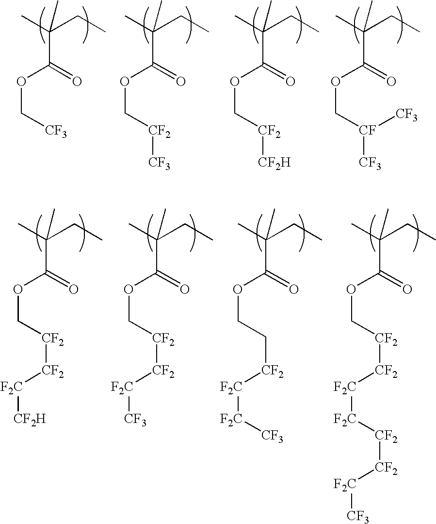
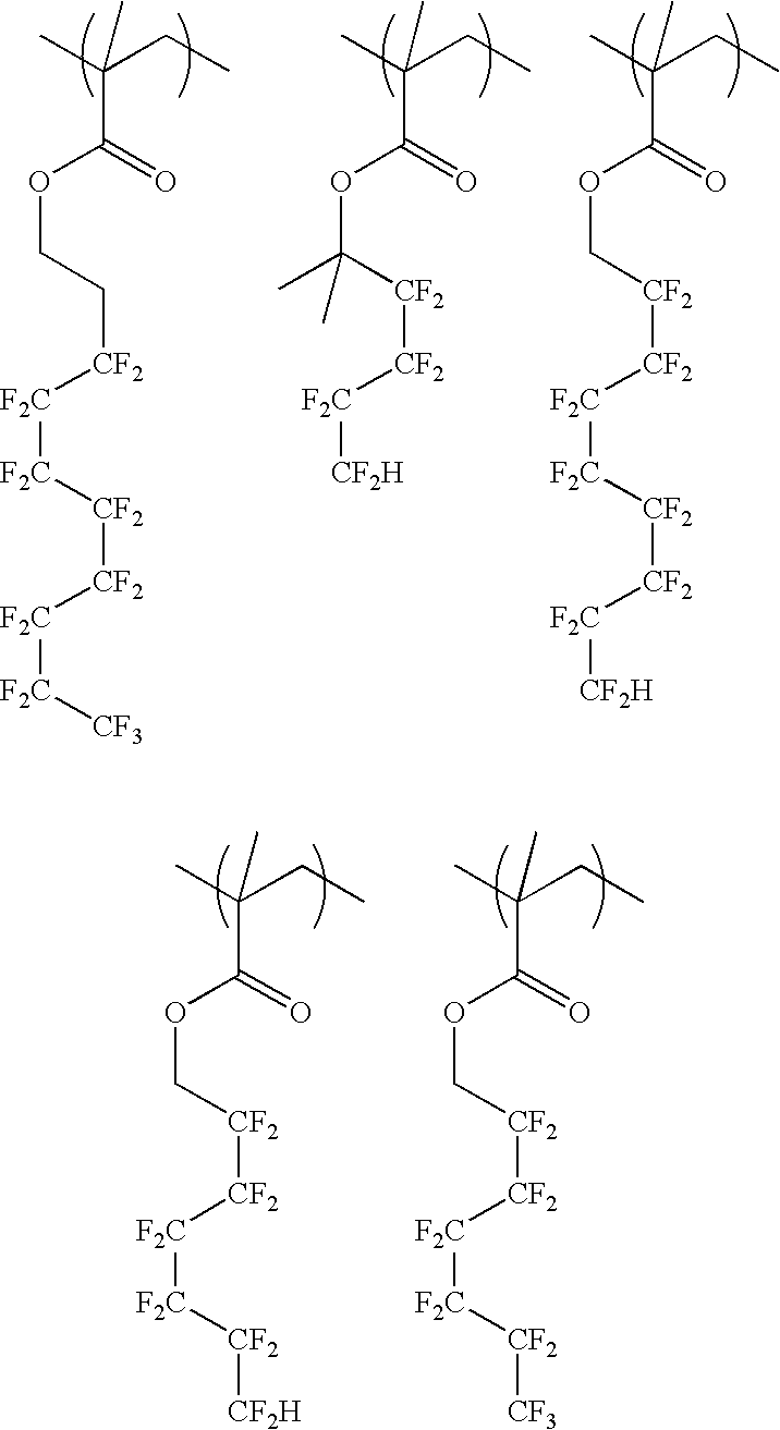
[0056] A 200-ml flask was charged with 38.7 g of Monomer 1, 6.7 g of Monomer 2 and 40 g of methanol as a solvent. This reaction vessel was cooled to −70° C. in a nitrogen atmosphere, followed by three time repetitions of vacuum deaeration and nitrogen flow. After heating to room temperature, 3 g of 2,2′-azobis(2,4-dimethylvaleronitrile) was added as a polymerization initiator. After heating to 65° C., the reaction was effected for 25 hours. The reaction solution was poured into hexane for crystallization, by which the resin was isolated. The composition and molecular weight of the resulting resin were confirmed by 1H-NMR and GPC, respectively. The resin was designated as Example Polymer 1.

synthesis example 2

[0057] A 200-ml flask was charged with 38.7 g of Monomer 1, 12.3 g of Monomer 3 and 40 g of methanol as a solvent. This reaction vessel was cooled to −70° C. in a nitrogen atmosphere, followed by three time repetitions of vacuum deaeration and nitrogen flow. After heating to room temperature, 3 g of 2,2′-azobis(2,4-dimethylvaleronitrile) was added as a polymerization initiator. After heating to 65° C., the reaction was effected for 25 hours. The reaction solution was poured into hexane for crystallization, by which the resin was isolated. The composition and molecular weight of the resulting resin were confirmed by 1H-NMR and GPC, respectively. The resin was designated as Example Polymer 2.

synthesis example 3

[0058] A 200-ml flask was charged with 30.3 g of Monomer 2, 7.7 g of Monomer 8 and 40 g of methanol as a solvent. This reaction vessel was cooled to −70° C. in a nitrogen atmosphere, followed by three time repetitions of vacuum deaeration and nitrogen flow. After heating to room temperature, 3 g of 2,2′-azobis(2,4-dimethylvaleronitrile) was added as a polymerization initiator. After heating to 65° C., the reaction was effected for 25 hours. The reaction solution was poured into hexane for crystallization by which the resin was isolated. The composition and molecular weight of the resulting resin were confirmed by 1H-NMR and GPC, respectively. The resin was designated as Example Polymer 3.


PUM

PropertyMeasurementUnit
domain sizeaaaaaaaaaa
exposure wavelengthaaaaaaaaaa
wavelengthaaaaaaaaaa

Abstract

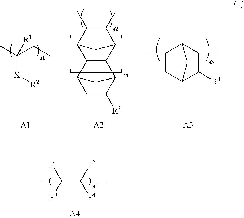
The invention is a protective film material for immersion lithography that enables desirable immersion lithography, can be removed simultaneously with development of a photoresist layer, and has excellent process adaptability. The invention also includes a method for forming a pattern using the material. More specifically, the invention is a protective film material comprising (i) a blend of a polymer comprising a repeating unit having a fluorine-containing alkyl or alkylene group which contains at least one fluorine atom and an optional alkali soluble repeating unit and a polymer comprising a repeating unit having a fluorine-free alkyl group and an optional alkali soluble repeating unit, or (ii) a polymer comprising a repeating unit having a fluorine-containing alkyl or alkylene group which contains at least one fluorine atom and a repeating unit having a fluorine-free alkyl group and an optional alkali-soluble repeating unit.

Description

BACKGROUND OF THE INVENTION [0001] 1. Field of the Invention [0002] The present invention relates to a resist protective film material to be used as a layer on or above a photoresist layer for protecting the photoresist layer in fine processing in the fabrication of a semiconductor device, particularly in immersion lithography of introducing water between a projector lens and a wafer and using an ArF excimer laser having a wavelength of 193 nm as a light source; and a method for forming a resist pattern using the material. [0003] 2. Description of the Related Art [0004] In the recent drive for higher integration and higher operation speed in LSI devices, a demand for a finer pattern rule is high. However, light exposure which is currently on widespread use in the art is approaching the essential limit of resolution determined by the wavelength of a light source. As the exposure light for the formation of a resist pattern, g-line (436 nm) or i-line (365 nm) from a mercury lamp was wi...

Claims


Application Information

Patent Timeline
Patent Type & Authority Applications(United States)
IPC IPC(8): G03C1/00
CPCG03F7/0046G03F7/11G03F7/2041G03F7/09
Inventor HATAKEYAMA, JUNHARADA, YUJIWATANABE, TAKERU
Owner SHIN ETSU CHEM IND CO LTD
Why Eureka
Try Eureka