Metal-based carbon fiber composite material and method for producing the same

a carbon fiber and composite material technology, applied in the field of metal-based carbon fiber composite materials, can solve the problems of carbon fibers reacting with metals, increasing the amount of heat generated by equipment, and generating metal carbides, and achieves the effects of low weight, high thermal conductivity, and inhibiting the formation of metal carbides

Inactive Publication Date: 2007-06-21
SHIMANE PREFECTURAL GOVERNMENT MATSUE
View PDF10 Cites 16 Cited by
  • Summary
  • Abstract
  • Description
  • Claims
  • Application Information

AI Technical Summary

Benefits of technology

[0015] By employing the above-described constitution, it become possible to obtain a metal-based carbon fiber composite material which is light in weight and high in thermal conductivity. The obtained composite material is useful as a heat-dissipating member (base plate, heat sink, heat spreader or the like) for semiconductor-used electronic equipment and a power module. Further, the method of the present invention requires no particular additional steps or materials. The inventive method can inhibit the formation of metal carbides resulting from the reaction of metal with carbon fiber. Consequently, the present method can provide a metal-based carbon fiber composite material having excellent properties in a simple and inexpensive manner. Further, in the metal-based carbon fiber composite material of the present invention where the carbon fiber is aligned, it is possible to control the direction of heat flow on the basis of the aligning direction: of the carbon fiber. This characteristic is particularly effective in suppressing the heat flow to adjacent devices in a case of electronic equipment in which semiconductors are highly integrated

Problems solved by technology

However, there is a marked tendency that an amount of heat generated from the equipment increases in association with sophistication of the equipment.
In forming a metal-based carbon fiber composite material by a liquidized metal impregnation method, there is a problem that carbon fibers react with metal in the liquidized metal to generate metal carbides.
It is also known that the voids greatly reduce the strength and the thermal conductivity of the composite material.

Method used


Image

  • Metal-based carbon fiber composite material and method for producing the same
  • Metal-based carbon fiber composite material and method for producing the same
  • Metal-based carbon fiber composite material and method for producing the same

Examples


example 1

[0054] To a rod mill having an inner diameter of 13 mm was added 6 grams of aluminum powder having a mean particle diameter of 30 μm (available from Kishida Chemical Co., Ltd. ), 3 grams of pitch-based carbon fiber having a fiber length of 20 μm and a diameter of 10 μm (available from Nippon Graphite Fiber Corporation, YS-95A) and a glass rod (5 mm in diameter×20 mm in length). The rod mill was rotated along its axis to mix the ingredients, thereby obtaining a metal fiber mixture.

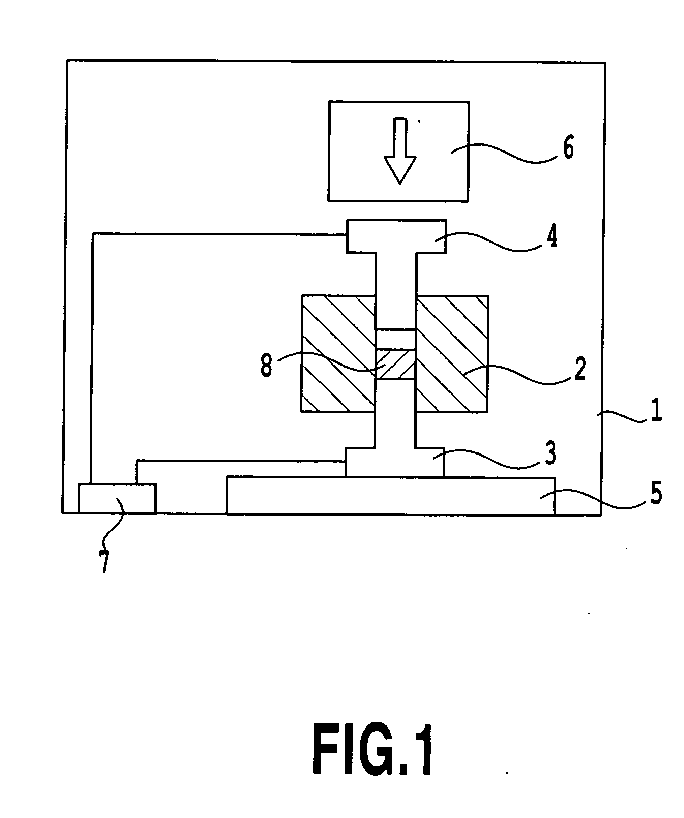
[0055] Next, the metal fiber mixture was filled into the equipment shown in FIG. 1, and a pressure in the equipment is set to 8 Pa. The die having a through hole of 20×20 cm was used in this example. Into the die is fitted the lower punch to form a recess, and the metal fiber mixture was filled into the recess such that carbon fiber was aligned in one direction. Next, the upper punch was placed on the filled metal fiber mixture, and pressure of 25 MPa was applied by using the plunger.

[0056] Then, pulse el...

example 2

[0058] The same procedures as described in Example 1 are repeated, except that the amount of carbon fiber is changed to 4 grams and that of aluminum powder was changed to 4 grams. The obtained metal-based carbon fiber composite material contained 60% of carbon fiber based on a total weight of the composite material and had a density of 1.75 g / cm3. The composite material had an ideal density of 2.38 g / cm3 and a relative density of 73%. The composite material had a thermal conductivity of 300 W / mK, as measured in the aligning direction of the carbon fiber.

example 3

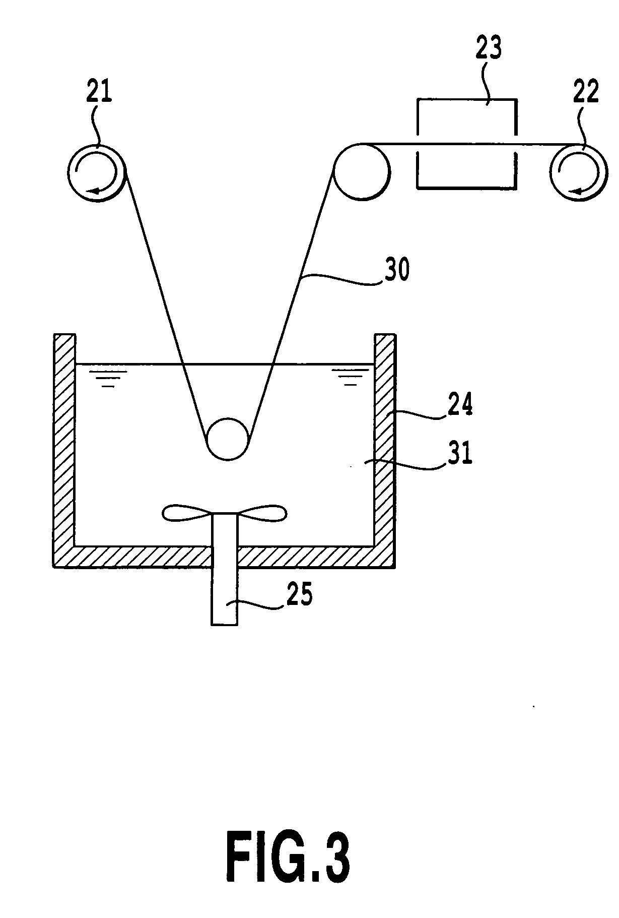
[0059] In this example, a suspension immersion method was used to prepare a metal fiber mixture, in which an aluminum powder suspension was applied to carbon fiber that can be handled as continuous fiber. The metal fiber mixture was sintered in the pulsed electric current sintering method to provide a metal-based carbon fiber composite material.

[0060] Pitch-based carbon fiberhaving a thermal conductivity of 1000 W / mK and a diameter of 10 μm was used as carbon fiber and a bundle made of 6000 pieces of the fiber was wound up around an unwinding bobbin 2. Flake-like powder, which is 1 μm or less in thickness and 30 μm in mean representative length toward a surface (in-plane) direction, was used as aluminum powder. The aluminum powder was mixed in ethanol containing 2% by weight (based on weight of the ethanol) of a dispersant-adhesive (Pluronic (registered trade mark) F68) to form a metal powder suspension. The content of aluminum powder was 30% by weight based on the weight of the su...


PUM

PropertyMeasurementUnit
densityaaaaaaaaaa
densityaaaaaaaaaa
densityaaaaaaaaaa

Abstract

A method is provided for producing a metal-based carbon fiber composite material lightweight, high in the thermal conductivity and also capable of controlling the direction of heat flow, while inhibiting metal carbide formation. The method for producing the metal-based carbon fiber composite material comprises the steps of: obtaining a metal fiber mixture by physically mixing carbon fiber with metal powder; filling the metal fiber mixture into a jig, while the metal fiber mixture is aligned; and setting the jig in an air, vacuum or inert gas atmosphere and directly supplying pulse electric current to the metal fiber mixture, with applying a pressure, to effect sintering by the heat generated therefrom. Here, the composite material contains 10 to 80% by weight of carbon fiber based on a total weight of the composite material and is sintered at 70% or more of ideal density.

Description

TECHNICAL FIELD [0001] carbon fiber composite material. More specifically, the present invention relates to a metal-based carbon fiber composite material having a high thermal conductivity suitable in dissipating the heat from equipment working from ordinary temperature to several hundred degrees Celsius of temperature and a method for producing the metal-based carbon fiber composite material by using a pulsed electric current sintering. BACKGROUND ART [0002] Conventionally, metals such as aluminum and copper having a high thermal-conductivity or their alloys have been used in heat-dissipating members (base plate, heat sink, heat spreader and the like) for semiconductor-used electronic equipment and a power module. However, there is a marked tendency that an amount of heat generated from the equipment increases in association with sophistication of the equipment. Further, heat-dissipating members have been required to be made smaller in size and lighter in weight, as the equipment i...

Claims


Application Information

Patent Timeline
Patent Type & Authority Applications(United States)
IPC IPC(8): D04H1/00B22F3/14C22C47/14C22C49/14H01L23/373
CPCB22F2003/1051B22F2998/00B22F2999/00B82Y10/00B82Y30/00H01L2924/0002C22C47/14C22C49/14C22C2026/002C22C47/025C22C26/00B22F3/14B22F3/105B22F2201/10B22F2201/20H01L2924/00Y10T428/249924H01L23/373
Inventor SATO, KIMINORIOZOE, NOBUAKIOGAWA, JINICHIUENO, TOSHIYUKIKOMATSUBARA, SATOSHI
Owner SHIMANE PREFECTURAL GOVERNMENT MATSUE
Why Eureka
Try Eureka