Methods and apparatus for the sytematic control of ventilatory support in the presence of respiratory insufficiency

a ventilatory support and respiratory insufficiency technology, applied in the field of sytematic control of ventilatory support in the presence of respiratory insufficiency, can solve the problems of lowering the arterial partial pressure of oxygen, worse gas exchange during sleep, and increasing the arterial partial pressure of carbon dioxide, so as to reduce the gain, reduce the loss, and reduce the effect of ventilatory support respons

Active Publication Date: 2007-07-19
RESMED LTD
View PDF17 Cites 61 Cited by
  • Summary
  • Abstract
  • Description
  • Claims
  • Application Information

AI Technical Summary

Benefits of technology

[0028] Another aspect of the invention relates to the delivery of servo-controlled ventilatory support to maintain a target ventilation. Adjustment of the delivered ventilatory support is based on the error between a target and actual measure, and a gain which varies with the distance of the actual measure from the target. Alternatively, it may be a function of relative ventilation error (which is defined to be ventilation error divided by target ventilation). This varying gain permits subdued ventilatory support responses for mild changes in patient ventilation while permitting more vigorous responses to more severe changes. In a simple form, a step function provides a lower gain if the distance from the target is less than a threshold and higher gain otherwise. The gain may be altered symmetrically around the target or alternatively asymmetrically. In an asymmetrical embodiment, the gain may change differently depending on whether the patient's ventilation is above or below the desired or target ventilation. These tempered or graduated gain adjustments permit the device to make a relatively greater increase (i.e., a more aggressive response) in pressure support when measured ventilation is further from the target, i.e., there is a large target error, than when measured ventilation is closer to the target, i.e., there is a small target error. It also permits making less aggressive changes to the gain for hyperventilation and more aggressive changes for hypoventilation.
[0029] In another aspect of the invention, control of ventilation is more accurately achieved by controlling a measure of alveolar ventilation. Since the airways contain dead space, only a portion of the air inhaled by a patent can participate in gas exchange. In accordance with the invention, the total ventilation is corrected by subtracting the effect of anatomical and / or physiological dead space as an estimate of a target alveolar ventilation. This alveolar ventilation is utilized as a target and compared with a similarly calculated actual measure made during the delivery of ventilatory support. The target error of these two terms is then applied to adjust the pressure support provided by the ventilator.

Problems solved by technology

Respiratory insufficiency is an abnormality of the respiratory system with an adverse effect on gas exchange, resulting in a lowering of the arterial partial pressure of oxygen, an increase in the arterial partial pressure of carbon dioxide, or both.
Respiratory insufficiency generally results in worse gas exchange during sleep, for a variety of reasons including decreased respiratory drive and postural factors.
Apneas and hypopneas interfere with gas exchange, fragment sleep, and frequently cause oxygen desaturations.
A problem with ventilators that target total ventilation (traditionally called “minute ventilation”) is that total ventilation may not provide an accurate measure of the extent to which the actual needs of the patient are met.
Such a measure does not account for the fact that patients have anatomical and physiological deadspace, and that the deadspace varies between patients.
A device which servocontrols minute ventilation is thus at risk of providing inadequate alveolar ventilation at high respiratory rates.

Method used


Image

  • Methods and apparatus for the sytematic control of ventilatory support in the presence of respiratory insufficiency
  • Methods and apparatus for the sytematic control of ventilatory support in the presence of respiratory insufficiency
  • Methods and apparatus for the sytematic control of ventilatory support in the presence of respiratory insufficiency

Examples


Embodiment Construction

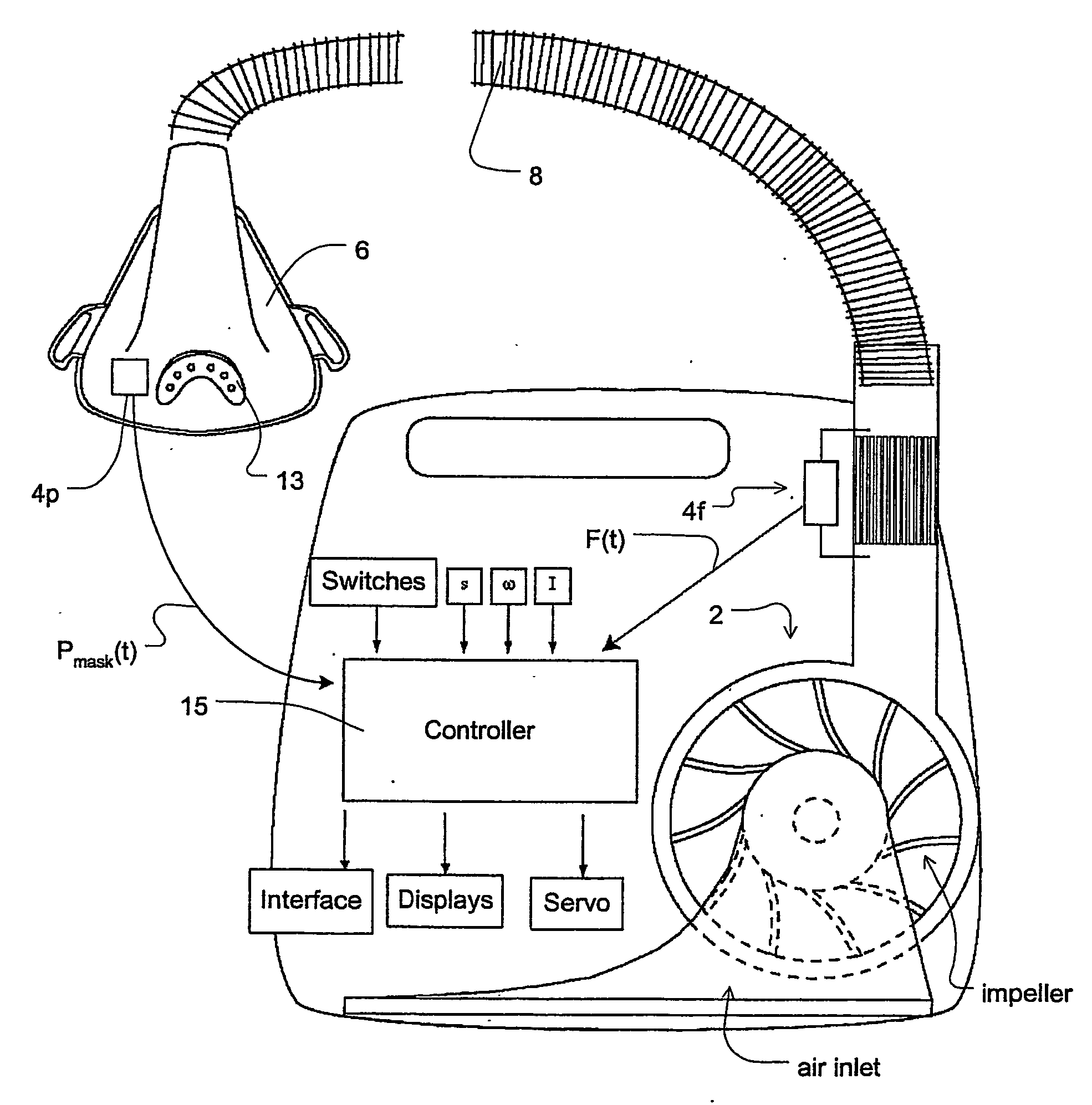
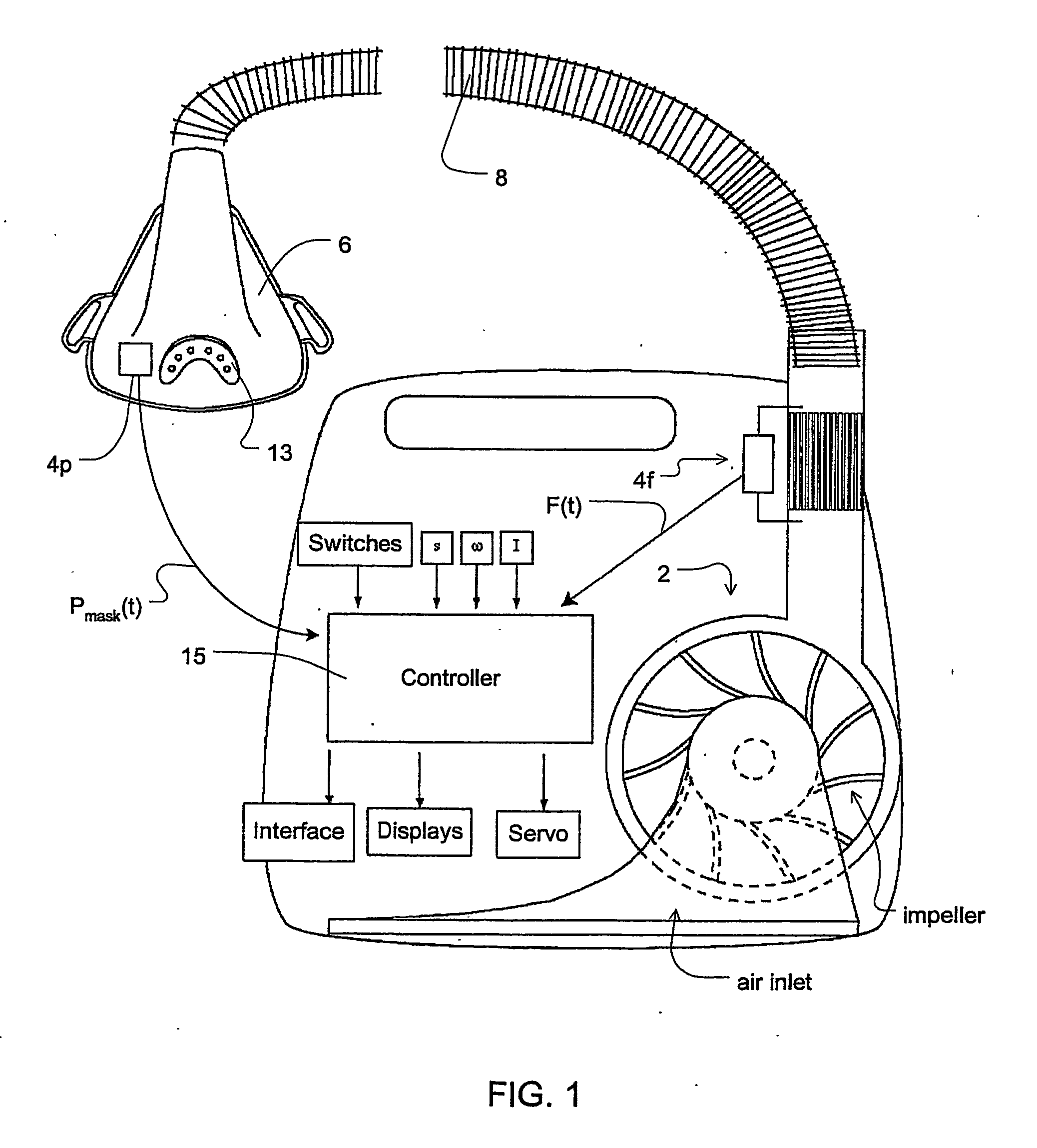
[0038] In reference to FIG. 1, the ventilator relies on a servo-controlled loop for governing the operation of blower 2. The device includes a flow sensor 4f, pressure sensor 4p, a mask 6, and an air delivery conduit 8 for connection between the blower 2 and the mask 6. Exhaust gas is vented via exhaust 13. Mask flow may be measured using a pneumotachograph and differential pressure transducer to derive a flow signal F(t). Alternatively, the pneumotachograph may be replaced by a bundle of small tubes aligned in parallel with the flow. from the blower with the pressure difference measured by the differential pressure transducer across the bundle. Mask pressure is preferably measured at a pressure tap using a pressure transducer to derive a pressure signal Pmask(t). The pressure sensor 4f and flow sensor 4p have been shown only symbolically in FIG. 1 since those skilled in the art will understand how to measure flow and pressure. Flow F(t) and pressure Pmask(t) signals are sent to a c...


PUM


Abstract

A method and apparatus for providing ventilatory assistance to a spontaneously breathing patient An error signal (56) is computed that is the difference between a function of respiratory airflow (54) over a period of time and a target value (52). Using a servo loop, air is delivered to the patient at a pressure that is a function of the error signal, the phase of the current breathing cycle, and a loop gain that varies depending on the magnitude of the error signal. The loop gain increases with the magnitude of the error signal, and the gain is greater for error signals below a ventilation target than for error signals above the ventilation target value. The target value (52) is an alveolar ventilation that takes into account the patient's physiologic dead space.

Description

[0001] This application claims the benefit of U.S. provisional application No. 60 / 525,219, filed Nov. 26, 2003.FIELD OF THE INVENTION [0002] This invention relates to methods and apparatus for the provision of ventilatory assistance synchronized with a patient's respiratory cycle and controlled to provide a minimum sufficient level of support in the presence of respiratory insufficiency. BACKGROUND OF THE INVENTION [0003] Respiratory insufficiency is an abnormality of the respiratory system with an adverse effect on gas exchange, resulting in a lowering of the arterial partial pressure of oxygen, an increase in the arterial partial pressure of carbon dioxide, or both. It may be due to a decrease in ventilation in the presence of normal lungs, a lung abnormality, or a combination of these. [0004] Respiratory insufficiency generally results in worse gas exchange during sleep, for a variety of reasons including decreased respiratory drive and postural factors. The decrease in voluntary...

Claims


Application Information

Patent Timeline
Patent Type & Authority Applications(United States)
IPC IPC(8): A61M16/00A62B7/00A61M16/06
CPCA61M16/00A61M16/06A61M2016/0039A61M2205/15A61M2205/50A61M2016/0033A61M16/0069A61M16/0051A61B5/087A61M16/0003A61M2230/005A61M2230/40A61M16/0875A61M16/024
Inventor BASSIN, DAVID
Owner RESMED LTD
Why Eureka
Try Eureka