Light emitting apparatus and light emitting method

a technology of light emitting apparatus and light emitting method, which is applied in the direction of discharge tube luminescnet screen, instruments, sustainable buildings, etc., can solve the problems of low spectrum intensity, low color rendering property, and oxidized system phosphors, so as to improve the color rendering property

Active Publication Date: 2007-07-19
TOYODA GOSEI CO LTD
View PDF5 Cites 74 Cited by
  • Summary
  • Abstract
  • Description
  • Claims
  • Application Information

AI Technical Summary

Benefits of technology

[0026] It is an object of the invention to provide light emitting apparatus and light emitting method that can improve the color rendering property as to red color.
[0027] It is another object of the invention to provide light emitting apparatus and light emitting method that can enhance the brightness of white LED.

Problems solved by technology

Therefore, it lacks in color rendering property as to red color.
Also, oxide system phosphors generally have a problem that the spectrum intensity lowers significantly when the excitation wavelength exceeds 400 nm.
Therefore, in white LED that YAG system oxide phosphor is coated on the surface of InGaN system blue LED, the excitation energy of YAG system oxide phosphor does not coincide with the excitation energy of blue LED light source, and therefore the excitation energy cannot be efficiently converted.
Thus, it is difficult to enhance the brightness of white LED.

Method used


Image

  • Light emitting apparatus and light emitting method
  • Light emitting apparatus and light emitting method
  • Light emitting apparatus and light emitting method

Examples


first embodiment

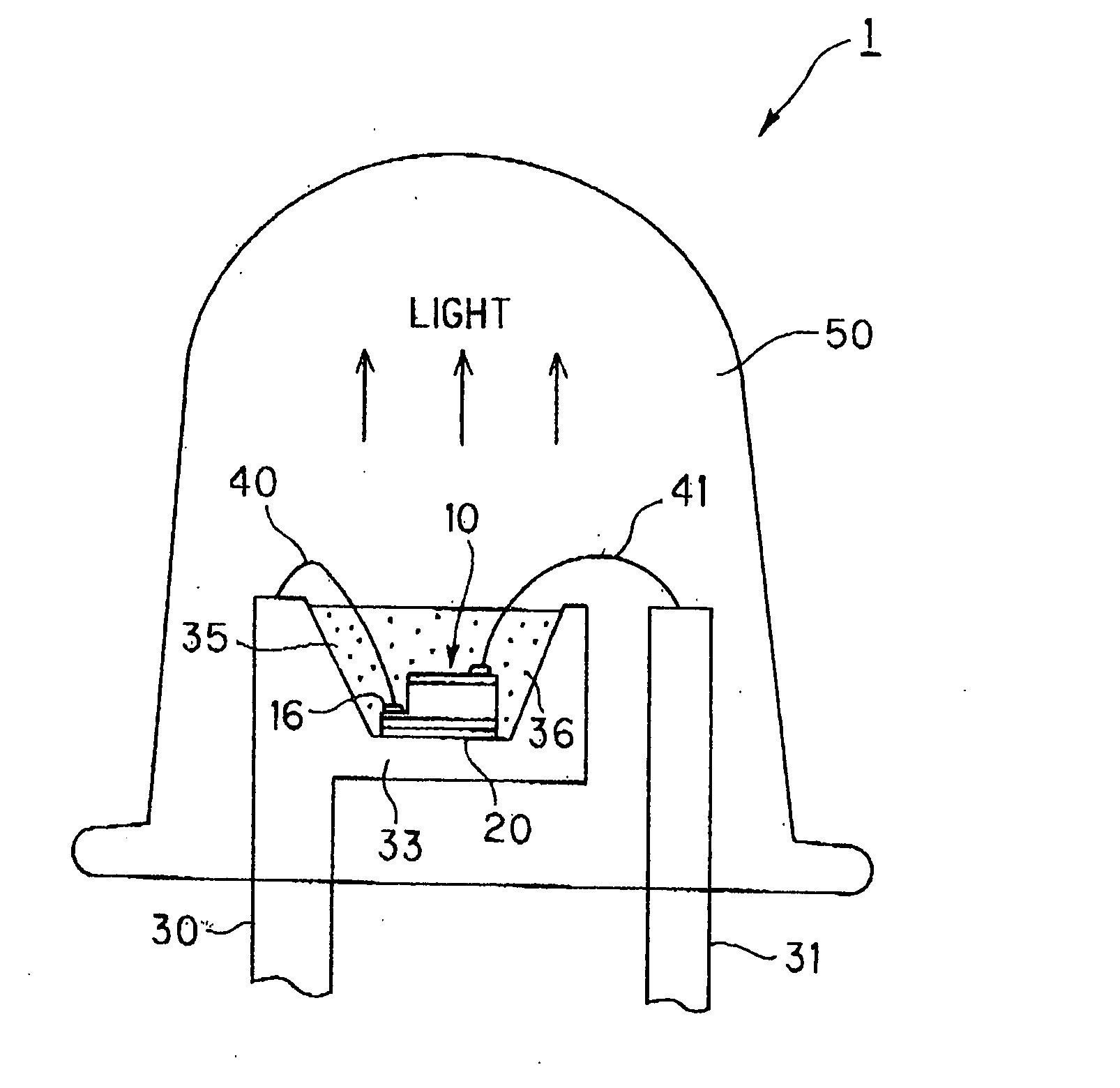
[0095]FIG. 1 is an illustration showing a lamp type (or shell type) LED as a light emitting apparatus in the first preferred embodiment according to the invention.

[0096] As shown in FIG. 1, the lamp type LED 1 is composed of: lead frames 30, 31; a light emitting element 10 that is mounted through adhesive 20 on a cup portion 33 of the lead frame 30; boding wires 40, 41 that connect between the lead frames 30, 31 and n-electrode, p-electrode of light emitting element 10; epoxy resin 35 (hereinafter referred to as phosphor resin), which contains phosphor 36 dispersed uniformly, filled in the cup portion 33; and sealing resin 50 of epoxy resin that seals the light emitting element 10, part of lead frames 30, 31 and bonding wires40, 41. The LED 1 emits white series light and can be applied to, for example, a planar light source and a linear light source in combination with a light guiding member and further applied to various display devices.

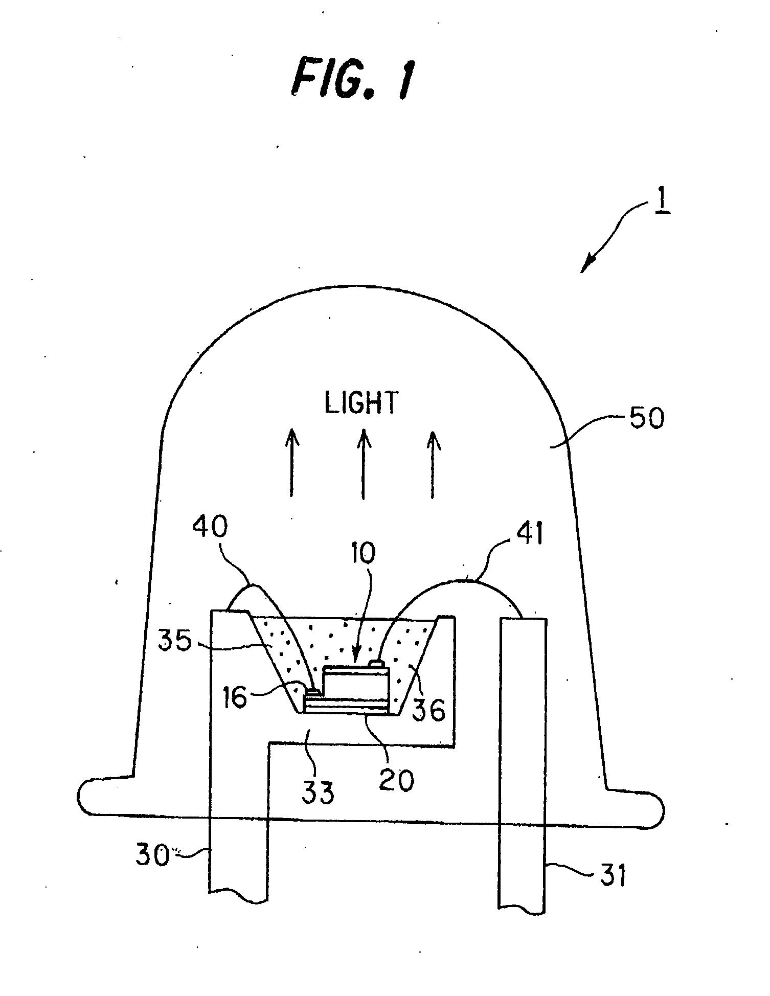
[0097] The light emitting element 10 and ph...

second embodiment

[0191]FIG. 10 is a cross sectional view showing a chip-type LED as a light emitting apparatus in the second preferred embodiment according to the invention. Like components are indicated by same numerals used in lamp-type LED 1 of the first embodiment.

[0192] LED 2 shown in FIG. 10 also emits white light like the lamp-type LED 1 and can be applied to, for example, a planar light source and a linear light source in combination with a light guiding member, and further applied to various display devices.

[0193] The light emitting element 10 is mounted on a substrate 80 through Ag paste etc. Electrodes (not shown) of light emitting element 10 are connected through wires 40, 41 to electrodes 80, 81 provided on the substrate 80. 90 is a reflection plate disposed around the light emitting element and the surface thereof is mirrored.

[0194] The cup portion formed by the substrate 80 and reflection plate 90 is filled with sealing resin 85. The light emitting element 10 and wires 40, 41 are s...

third embodiment

[0204]FIG. 14 is a cross sectional view showing a reflection-type LED 6 as a light emitting apparatus in the third preferred embodiment according to the invention. Like components are indicated by same numerals used in the lamp-type LED 1 of the first embodiment.

[0205] As shown in FIG. 14, the reflection-type LED 6 has a reflection mirror 110 on concave surface 111 of which phosphor layer 112 is formed. The phosphor layer 112 is of epoxy resin including phosphor 36 and is formed by coating. It may be of light transmitting material such as silicon resin and urea resin, other than epoxy resin and may be formed by vapor deposition, printing etc., other than coating. The phosphor layer may be formed on convex surface 113 of the reflection mirror 110. In this case, the reflection mirror 110 is formed using a light transmitting material and the surface of phosphor layer is mirrored. The mirroring is conducted forming a layer of metal with high reflection efficiency by vapor deposition, p...


PUM

PropertyMeasurementUnit
emission wavelengthaaaaaaaaaa
weight %aaaaaaaaaa

Abstract

A light emitting apparatus has a light emitting element with an emission wavelength in the range of 360 to 550 nm and a rare-earth element doped oxide nitride phosphor or cerium ion doped lanthanum silicon nitride phosphor. Part of light radiated from the light emitting element is wavelength-converted by the phosphor. The light emitting apparatus radiates white light generated by a mixture of the wavelength-converted light and the other part of light radiated from the light emitting element.

Description

[0001] The present application is based on Japanese patent application No. 2002-349286, the entire contents of which are incorporated herein by reference. [0002] The present application is a divisional of U.S. patent Ser. No. 10 / 722,563.BACKGROUND OF THE INVENTION [0003] 1. Field of the Invention [0004] This invention relates to light emitting apparatus and light emitting method that can be applied to a field requiring reliability such as disaster prevention light and traffic light, a field requiring light weight and small size such as in-vehicle light and LCD backlight and a field requiring visibility such as station guide plate, and more particularly to light emitting apparatus and light emitting method that has a structure with light emitting element and phosphor combined. [0005] 2. Description of the Related Art [0006] Conventionally, a light emitting apparatus is developed that part of light from light emitting element is wavelength-converted, then mixed with light not waveleng...

Claims


Application Information

Patent Timeline
Patent Type & Authority Applications(United States)
IPC IPC(8): H01L33/00C09K11/08C09K11/64C09K11/77C09K11/79C09K11/80H01L33/06H01L33/32H01L33/50H01L33/56H01L33/60H01L33/62
CPCC04B35/584H01L2924/12041C04B35/6455C04B2235/3208C04B2235/3217C04B2235/3224C04B2235/3225C04B2235/3852C04B2235/3865C04B2235/3869C04B2235/3873C04B2235/766C04B2235/80C09K11/0883C09K11/7734G02F2001/133614H01L33/502H01L2224/49107H01L2924/01025H01L2924/01079Y02B20/181H01L2924/01019H01L2924/01066H01L2924/01068C04B35/597Y02B20/00G02F1/133614C09K11/77348
Inventor YOSHIMURA, NAOKISUEHIRO, YOSHINOBUTAKAHASHI, YUJIOTA, KOICHIMITOMO, MAMORUENDO, TADASHIKOMATSU, MASAKAZU
Owner TOYODA GOSEI CO LTD
Why Eureka
Try Eureka