
Memory structure, memory device and manufacturing method thereof

a memory device and memory structure technology, applied in the field of high capacitance memory devices, can solve the problems of capacitor b>114/b>, capacitor charge loss is unavoidable, structure shrinkage, etc., and achieve the effect of reducing the frequency of refreshing the memory structure, improving the capacitance of the capacitor, and improving the accuracy of accessing data

Inactive Publication Date: 2007-07-19
UNITED MICROELECTRONICS CORP
View PDF3 Cites 0 Cited by
  • Summary
  • Abstract
  • Description
  • Claims
  • Application Information

AI Technical Summary

Benefits of technology

The present invention is about a method for manufacturing a memory structure with high capacitances. This method improves the accuracy of accessing data and reduces the frequency of refreshing the memory structure. The memory structure has a high capacitance, reducing the frequency of refreshing. The method involves forming a pattern in a dielectric layer, adding an amorphous silicon layer over the pattern, and patterning the amorphous silicon layer to form an electrode. A spacer is then formed on the sidewall of the electrode, followed by the formation of a selective hemispherical grains layer over the surface of the electrode and the spacer. The memory structure also includes a transistor and a memory cell with a bit line and a word line. The invention solves the problem of low surface area of the capacitor in the prior art and reduces the frequency of refreshing, improving the manufacturing yield.

Problems solved by technology

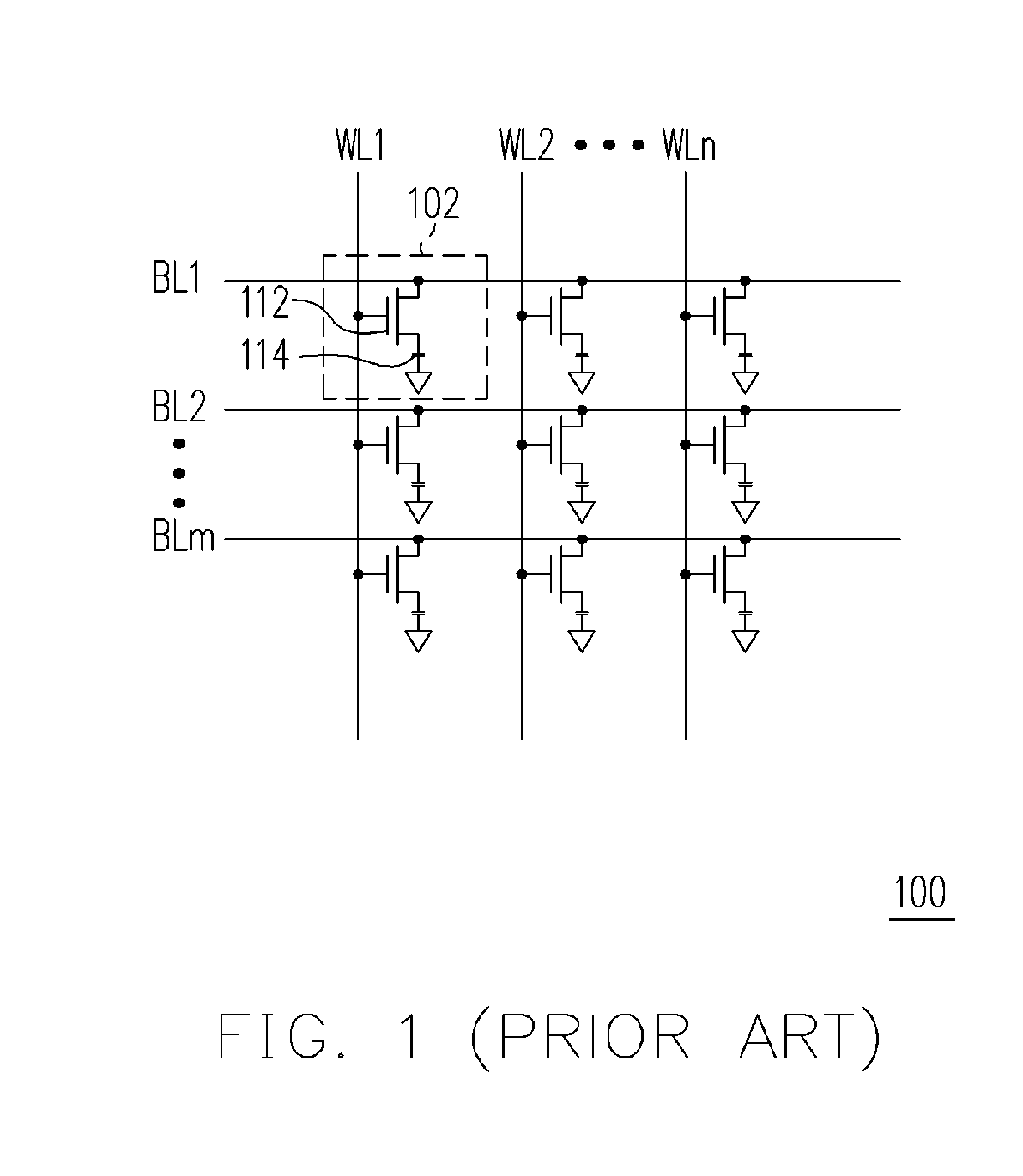
The shrinkage of the structure, however, will raise corresponding problems. FIG. 1 is a schematic drawing showing a conventional dynamic random access memory (DRAM).
In addition, the charge loss of the capacitor 114 is unavoidable due to the leakage current issue.
However, during the refresh step, the DRAM 100 cannot perform read or write operations.

Method used


Image

  • Memory structure, memory device and manufacturing method thereof
  • Memory structure, memory device and manufacturing method thereof
  • Memory structure, memory device and manufacturing method thereof

Examples


Embodiment Construction

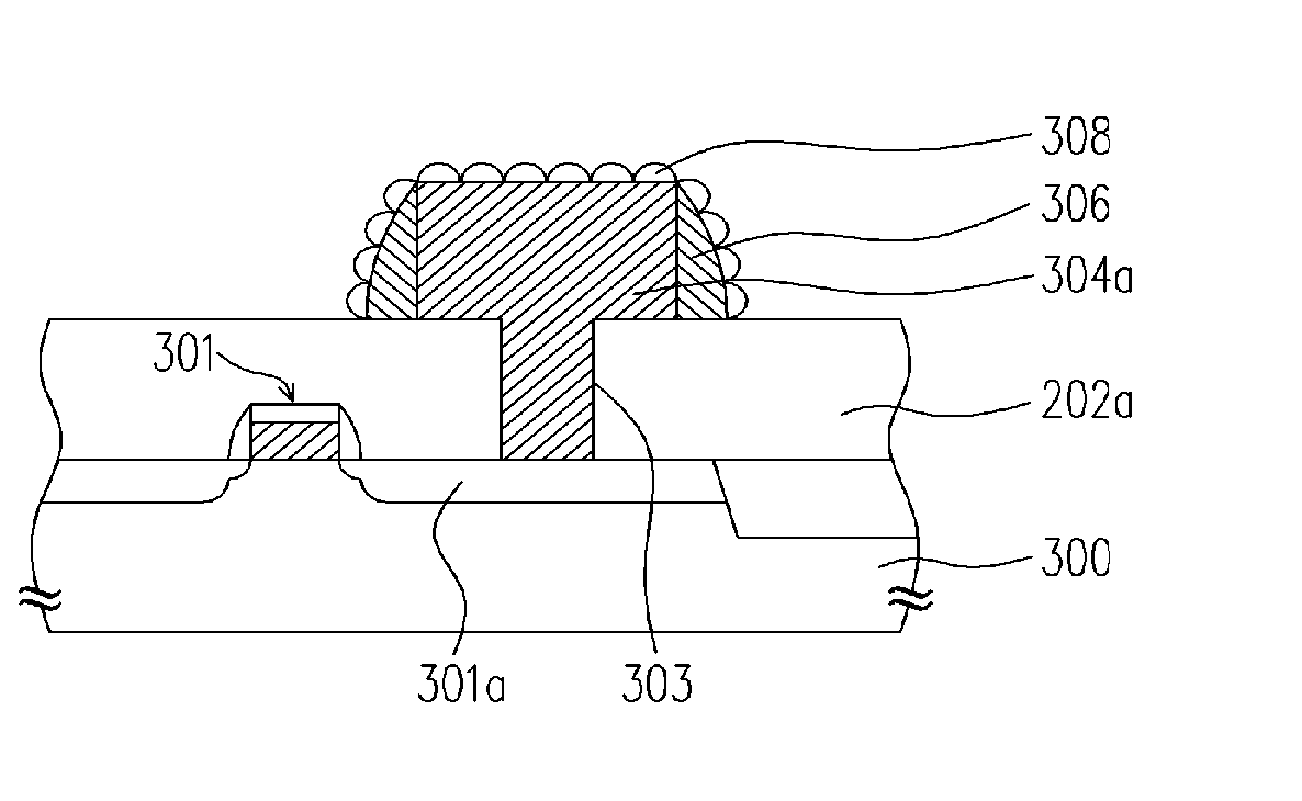
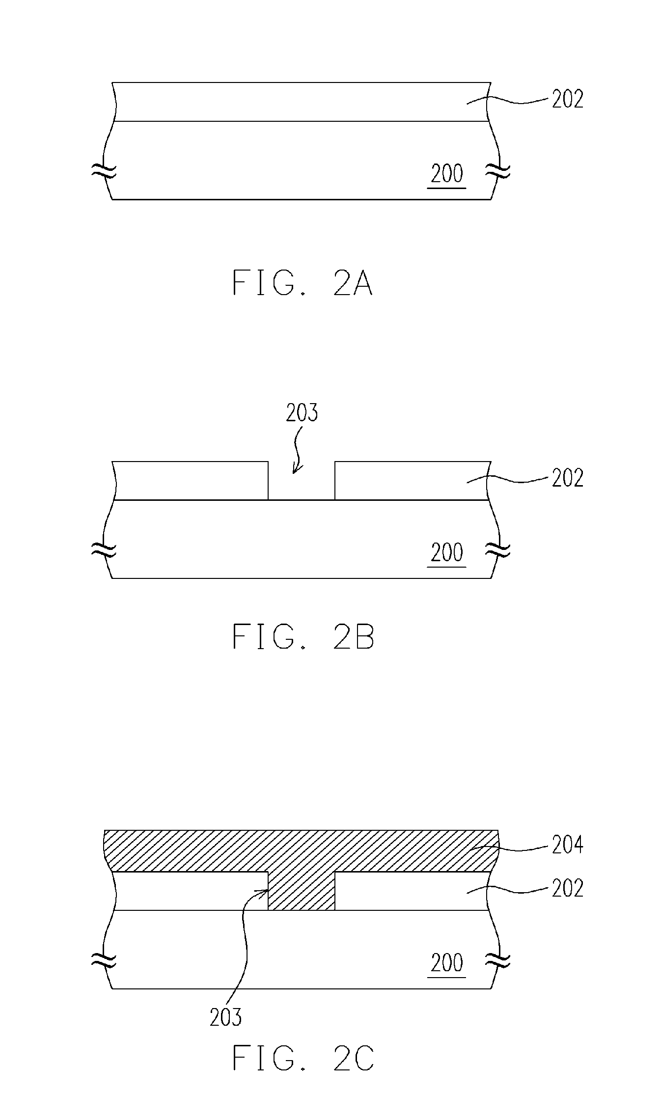
[0027] The present invention provides the memory with high capacitances due to the requirement of industrial development and process advance. Following are descriptions of the method for manufacturing the memory structure and memory device. FIGS. 2A-2E are schematic cross-sectional views showing a method for manufacturing a memory structure according to an embodiment of the present invention.

[0028] Referring to FIG. 2A, a dielectric layer 202 is formed over the substrate 200. A transistor (not shown) is formed over the substrate 200. Wherein, the material of the dielectric layer 202 can be, for example, silicon oxide, silicon nitride or silicon oxynitride. The method of forming the dielectric layer 202 can be a chemical vapor deposition (CVD) process, for example.

[0029] Referring to FIG. 2B, a contact window opening 203 is formed within the dielectric layer 202, wherein the method of forming the contact window opening 203 can comprise, for example, a photolithographic process and ...


PUM

PropertyMeasurementUnit
thicknessaaaaaaaaaa
thicknessaaaaaaaaaa
capacitanceaaaaaaaaaa

Abstract

A memory structure, a memory device and a manufacturing method thereof are provided. First, a substrate is provided and a dielectric layer is formed over the substrate. Then, a pattern is formed in the dielectric layer. An amorphous silicon layer is formed in the pattern and over the dielectric layer. The amorphous silicon layer is patterned to form an electrode over the pattern. Then, a spacer is formed on the sidewall of the electrode. A selective hemispherical grains (HSGS) layer is formed over the surface of the electrode and the surface of the spacer.

Description

BACKGROUND OF THE INVENTION [0001] 1. Field of the Invention [0002] The present invention relates to a semiconductor device and a manufacturing method thereof, and more particularly to a high capacitance memory device and a manufacturing method thereof. [0003] 2. Description of the Related Art [0004] As the integration of semiconductor technology advances, the size of semiconductor structures must be shrink to increase the density of devices in the integrated circuits. The shrinkage of the structure, however, will raise corresponding problems. FIG. 1 is a schematic drawing showing a conventional dynamic random access memory (DRAM). Referring to FIG. 1, the DRAM 100 comprises a plurality of memory units 102, bit lines BL1, BL2 to BLm, and word lines WL1, WL2 to WLn. Each of the memory units 102 is composed of a transistor 112 and a capacitor 114. Generally, each capacitor 114 of the corresponding memory units 102 is selectively charged or discharged through the transistor 112 to stor...

Claims


Application Information

Patent Timeline
Patent Type & Authority Applications(United States)
IPC IPC(8): H01L21/8244H10B10/00H10B12/00
CPCH01L27/105H01L27/1085H01L27/1052H01L28/84H01L27/10852H10B12/03H10B12/033
Inventor YANG, MING-TZONGLIAO, WAN-CHUNLEE, SHENG-CHINCHEN, HSIAO-LINLEE, CHIEN-HAOSHIU, SHR-WEI
Owner UNITED MICROELECTRONICS CORP
Learn More