
Methods of controlled acidization in a wellbore

Active Publication Date: 2007-07-26
HALLIBURTON ENERGY SERVICES INC
View PDF99 Cites 25 Cited by
  • Summary
  • Abstract
  • Description
  • Claims
  • Application Information

AI Technical Summary

Benefits of technology

[0003] Natural resources such as gas, oil, and water residing in a subterranean formation can be recovered by drilling wells into the formation. Well drilling involves drilling a wellbore down to the formation while circulating a drilling fluid through the wellbore. Various types of drilling fluids, also known as drilling muds, have been used in well drilling such as mineral oil-based fluids and synthetic oil-based fluids. Such drilling fluids typically form a thin, slick filter cake on the formation face that provides for successful drilling of the well bore and that helps prevent loss of fluid to the subterranean formation. In the hydrocarbon bearing portions of a formation, drilling fluids that produce filter cakes of cellulose and starch derivatives and sized calcium carbonate are often employed.
[0009] An improved acidization solution comprising an aqueous medium and one or more esters or polyesters of a hydroxy acid or of a glycerol may be placed in a well. In embodiments in which the solution comprises an ester or polyester of a glycerol, the solution is substantially absent of a hydrocarbon such as an oil. The hydrolysis of such esters or polyesters occurs at a slower reaction rate than that of other known acidization esters, such as diethyleneglycol diformate, at temperatures higher than 60° C. or even higher than 100° C. Thus, the improved acidization solution may be distributed substantially throughout a region in the well where acidization is required before hydrolysis is completed, despite being exposed to relatively high temperatures. The hydrolysis may result in the slow release of an acid that is capable of consuming undesirable substances in the well, e.g., a filter cake, without being concerned that this consumption might be localized. Moreover, the strength of this acid may be greater than that of the acid formed by diethyleneglycol diformate, i.e., formic acid. Accordingly, the use of esters or polyesters of hydroxy acid or of glycerol for downhole acidization procedures provides for the removal of all or most of the filter cake present in the well. BRIEF DESCRIPTION OF THE DRAWINGS

Problems solved by technology

However, at some point, pumps may be required to displace the oil from the wellbore to the surface.
Unfortunately, the presence of the filter cake on the face of the subterranean formation may adversely affect the flow of fluid though the injection and production wells.
In particular, the cellulose of which the filter cake is primarily composed may be decomposed by applying acid to the filter cake.
However, the high reactivity of such strong acids commonly result in the rapid consumption of the acid before it can reach the desired treatment region where the filter cake was located.
Further, such acids are highly corrosive and thus attack the metal parts of the well structure, causing irreversible damage to the well.
Unfortunately, such acids are as likely to be prematurely exhausted as mineral acids before reaching the desired treatment region.
However, this method is limited by the heat tolerance of the particular enzyme being used and the breakdown temperature of the acid precursor.
Treatment at high temperatures results in fast acid exhaustion and enzyme deactivation which results in poor filter cake removal.
Unfortunately, at elevated temperatures this release may occur in a relatively short period of time.
The esters currently being used for this purpose hydrolyze at relatively slow rates at temperatures less than 60° C. However, at higher temperatures those esters hydrolyze too quickly to allow the aqueous solution to be adequately dispersed across the entire filter cake before the acid is consumed.
The filter cake removal thus may be localized to a proportionately small area when using such methods, further resulting in the premature loss of the acid-generating fluid through pores that have been unclogged by this localized removal.
However, note that the present application may disclose multiple embodiments, and not all of the statements in this section necessarily relate to all of those embodiments.

Method used


Image

  • Methods of controlled acidization in a wellbore
  • Methods of controlled acidization in a wellbore
  • Methods of controlled acidization in a wellbore

Examples


example 1

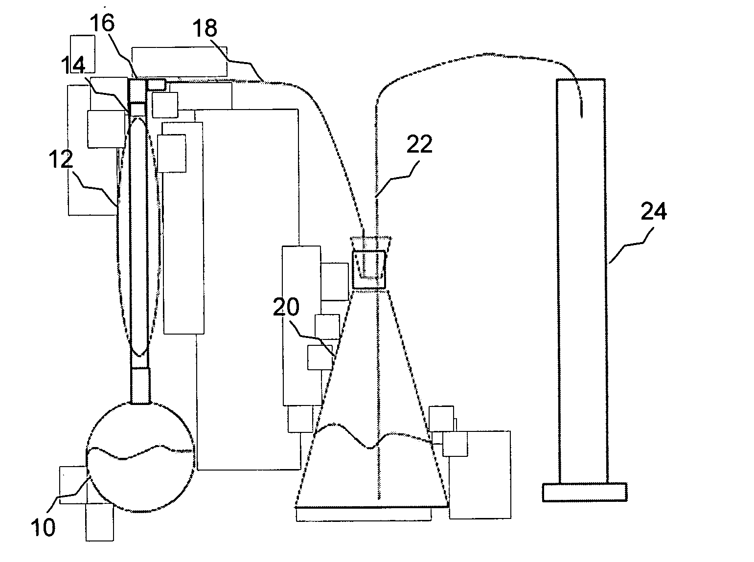
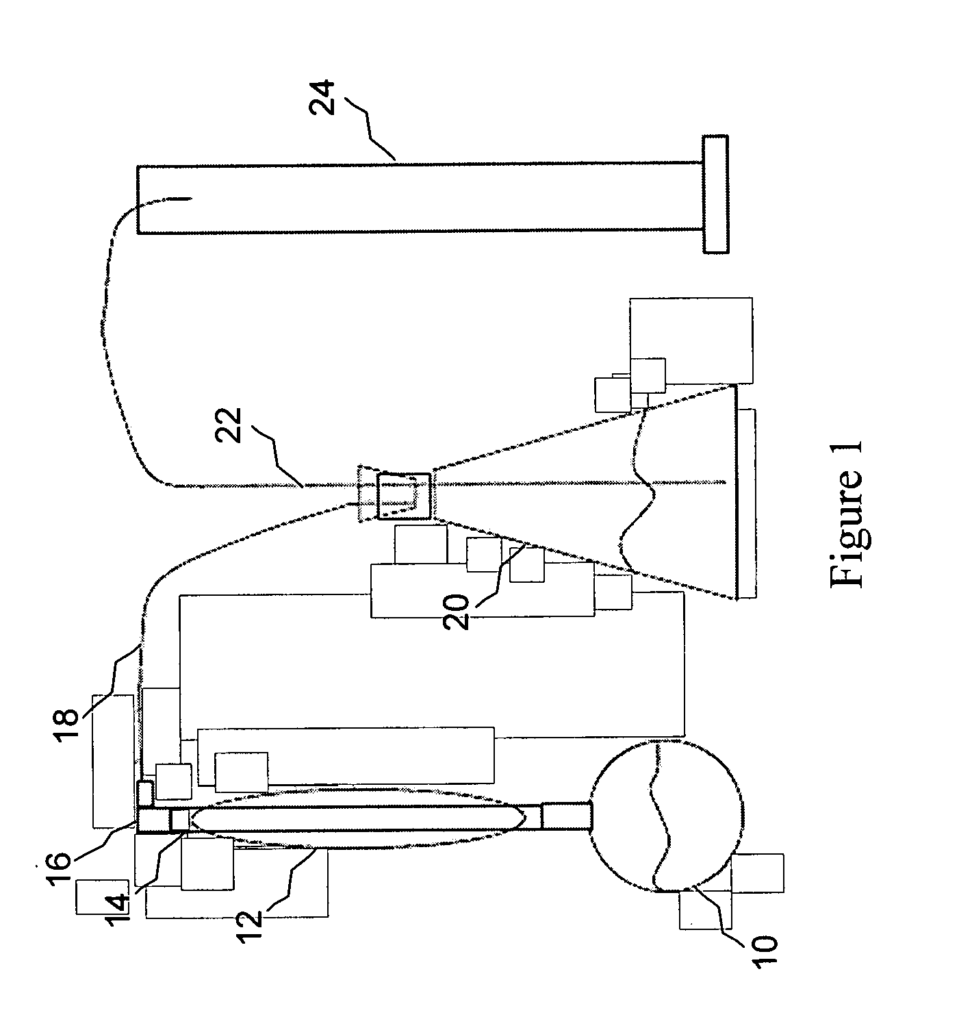
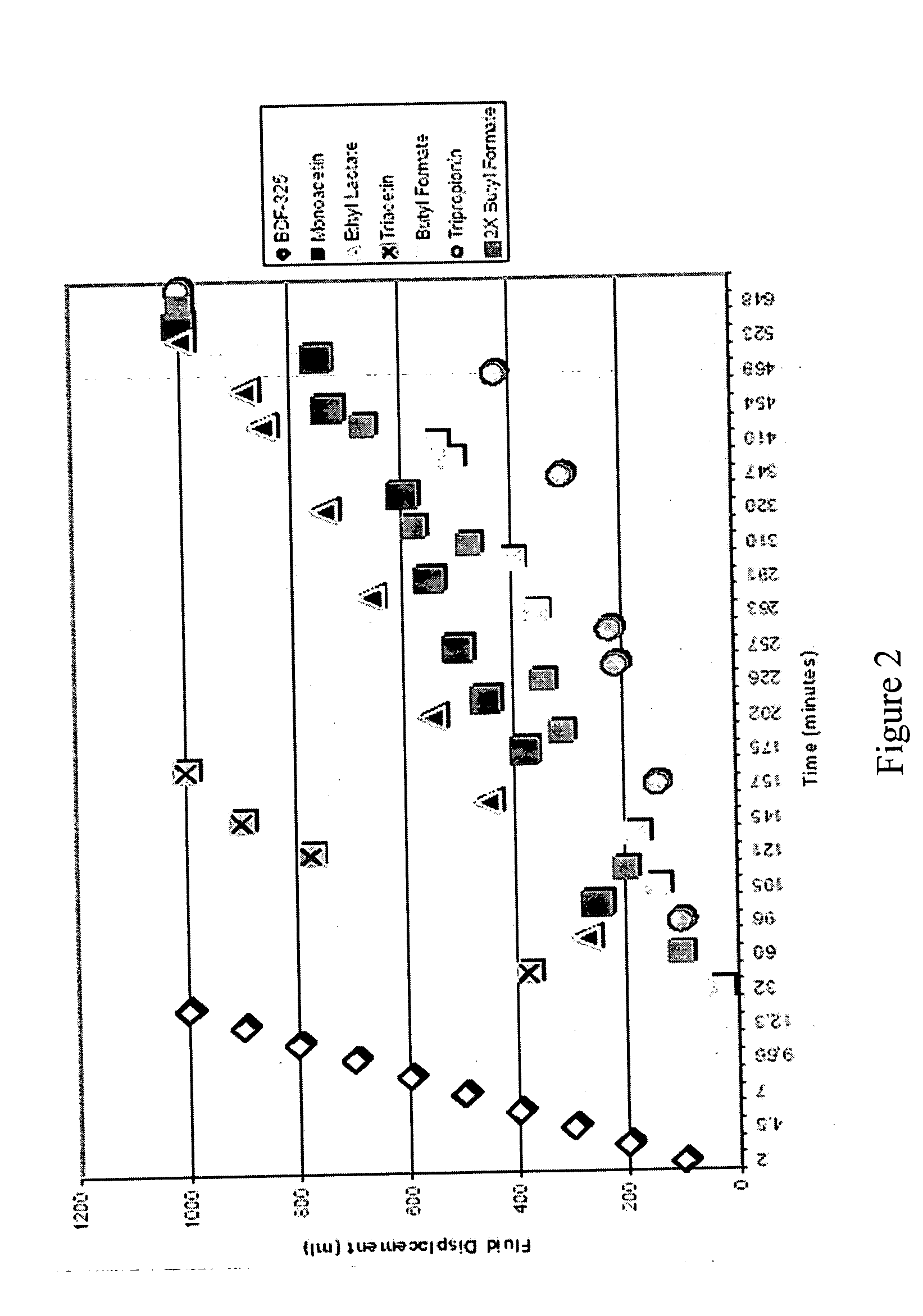
[0027] Solutions containing various esters of lactic acid and of glycerol (i.e., monoacetin, ethyl lactate, triacetin, tripropionin), butyl formate (a control), and BDF-325 diethyleneglycol diformate (a control) in neutral water were prepared and combined with a molar ratio of CaCO3. Hydrolysis reactions were then carried out using the resulting solutions at 100° C. The hydrolysis reactions were monitored, and the half-lives of the esters were compared. The volume of oil displaced by the CO2 gas is plotted as a function of time in FIG. 2. The half-lives of the esters of lactic acid and of glycerol were longer than that of the BDF-325 diethyleneglycol diformate. The butyl formate to CaCO3 molar ratio was doubled for comparison purposes. The curve for the 1:1 molar ratio reaction was surprisingly similar to that for the 2:1 molar ratio reaction. Doubling the molar ratio of the butyl formate should have lead to an increase in the relative reaction rate; however, this did not happen. It...

example 2

[0028] Solutions containing 10 volume % monoacetin, diacetin, and triacetin in deionized water were prepared and combined with a molar ratio of CaCO3. Hydrolysis reactions were then carried out using the resulting solutions at 100° C. The hydrolysis reactions were monitored, and the half-lives of the esters were compared. The volume of oil displaced by the CO2 gas is plotted as a function of time in FIG. 3. The hydrolysis rates of the triacetin and the diacetin were very similar. However, the monoacetin consumed 4-5 times more slowly relative to the other two acetins, and the monoacetin displayed a half-life within the targeted range. It is believed that the presence of the two hydroxyl groups in monoacetin slowed the rate of hydrolysis through hydrogen bonding with water. Another theory relies on the fact that monoacetin is a mixture of isomers. The acetate group may be on either a primary hydroxyl group or a secondary group. One isomer may be more reactive than the other. Despite ...

example 3

[0029] Solutions containing butyl lactate and butyl formate (a control) in deionized water were prepared and combined with a molar ratio of CaCO3. Similar solutions in which the butyl formate and butyl lactate to CaCO3 molar ratio were doubled were also prepared for comparison purposes. Hydrolysis reactions were then carried out using the resulting solutions at 100° C. The hydrolysis reactions were monitored, and the half-lives of the esters were compared. The volume of oil displaced by the CO2 gas is plotted as a function of time in FIG. 4. The reaction rate of the butyl lactate was faster than that of the butyl formate. This difference in reaction rates was probably due to the difference in solubilities of these two compounds in water. That is, butyl lactate is slightly soluble in water while butyl formate exhibits poor solubility in water. Doubling the concentration of butyl lactate doubled its reaction rate. The poor solubility of butyl formate governed its slow reaction rate, m...


PUM


Abstract

An improved acidization method is provided in which an aqueous solution comprising one or more esters or polyesters of lactic acid or of glycerol is placed in a well where the esters or polyesters undergo hydrolysis. The hydrolysis of the esters or polyesters occurs at a slower reaction rate than that of several other known acidization esters, such as diethyleneglycol diformate, at temperatures higher than 60° C. or even higher than 100° C. Thus, the solution may be distributed substantially throughout a region in the well where acidization is required before hydrolysis is completed, despite being exposed to relatively high temperatures. The hydrolysis may result in the slow release of an acid that is capable of consuming all or most of an undesirable substance in the well, e.g., a filter cake.

Description

FIELD OF THE INVENTION [0001] The present invention generally relates to hydrocarbon production, and more particularly to methods of obtaining controlled acidization in a well by placing an aqueous solution comprising one or more esters or polyesters of hydroxy acid or of glycerol in the well at locations where acidization is required. BACKGROUND AND SUMMARY OF THE INVENTION [0002] The following paragraphs contain some discussion, which is illuminated by the innovations disclosed in this application, and any discussion of actual or proposed or possible approaches in this Background section does not imply that those approaches are prior art. [0003] Natural resources such as gas, oil, and water residing in a subterranean formation can be recovered by drilling wells into the formation. Well drilling involves drilling a wellbore down to the formation while circulating a drilling fluid through the wellbore. Various types of drilling fluids, also known as drilling muds, have been used in ...

Claims


Application Information

Patent Timeline
IPC IPC(8): E21B43/27E21B37/00
CPCC09K8/72C09K8/52
Inventor MOOREHEAD, ALAN W.SHUMWAY, WILLIAM W.TODD, BRADLEY L.
Owner HALLIBURTON ENERGY SERVICES INC
Learn More