Direct oxidation fuel cell and method for operating direct oxidation fuel cell system
a fuel cell and direct oxidation technology, applied in the field of direct oxidation fuel cells and the method of operating a direct oxidation fuel cell system, can solve the problems of significant degradation of power generating characteristics, low fuel utilization efficiency, and commercialization of such direct methanol fuel cells, so as to reduce fuel crossover, improve power generation characteristics, and reduce fuel utilization efficiency
- Summary
- Abstract
- Description
- Claims
- Application Information
AI Technical Summary
Benefits of technology
Problems solved by technology
Method used
Image
Examples
embodiment 1
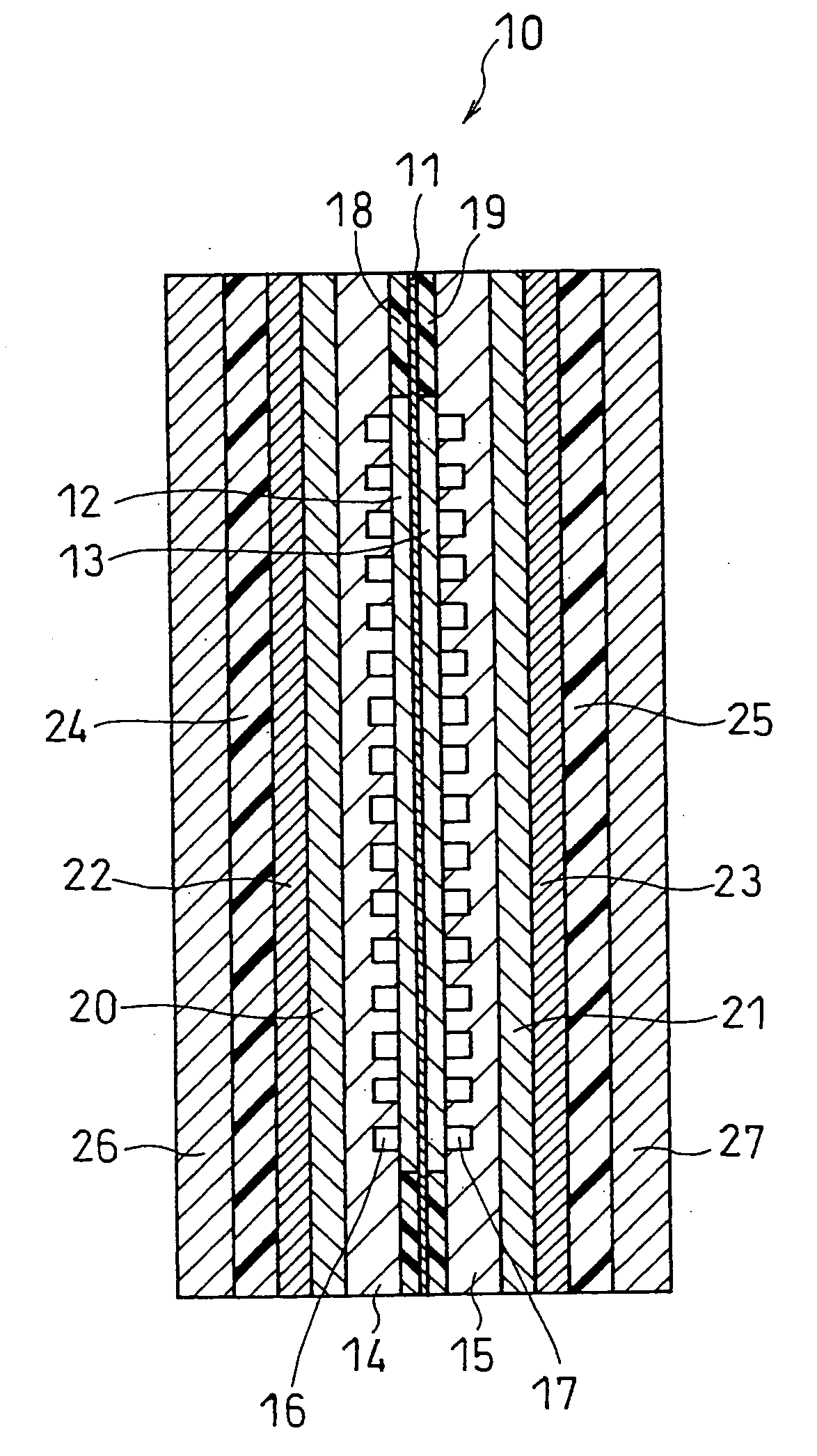
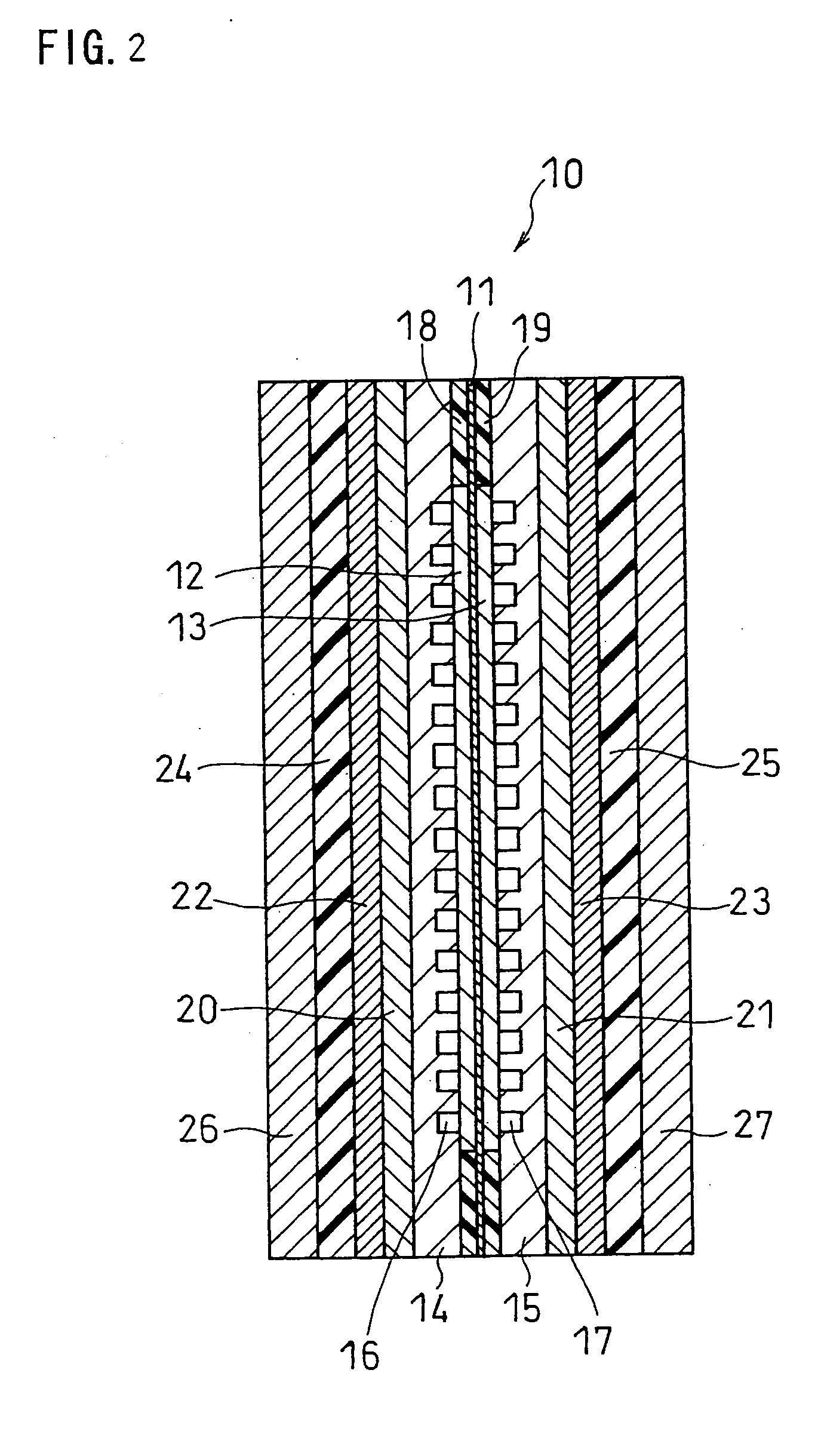
[0060]FIG. 2 is a schematic longitudinal sectional view showing the structure of a fuel cell in one embodiment of the present invention. In this example, the fuel cell is composed of one unit cell. A unit cell 10 includes a membrane electrode assembly (MEA) sandwiched between an anode-side separator 14 and a cathode-side separator 15. The MEA includes a hydrogen-ion conductive electrolyte membrane 11 and an anode 12 and a cathode 13 sandwiching the electrolyte membrane 11. Each of the anode and the cathode comprises a catalyst layer in contact with the electrolyte membrane and a diffusion layer on the separator side. The anode-side separator 14 has a flow channel 16, through which a fuel is supplied and discharged, on the anode-facing side thereof. The cathode-side separator 15 has a gas flow channel 17, through which an oxidant gas is supplied and discharged, on the cathode-facing side thereof. Gaskets 18 and 19 are fitted around the anode and the cathode so as to sandwich the elec...
example 1
[0077]Anode catalyst-carrying particles were prepared by placing 30% by weight of Pt and 30% by weight of Ru, each having a mean particle size of 3 nm, on carbon black (conductive carbon particles) with a mean primary particle size of 30 nm (ketjen black EC available from Mitsubishi Chemical Corporation). Also, cathode catalyst-carrying particles were prepared by placing 50% by weight of Pt with a mean particle size of 3 nm on the same ketjen black EC. Each of the anode and cathode catalyst-carrying particles was ultrasonically dispersed in an isopropanol aqueous solution. Each dispersion was mixed with a polymer electrolyte and then highly dispersed in a bead mill. In this way, an anode catalyst paste and a cathode catalyst paste were prepared. The weight ratio between the conductive carbon particles and the polymer electrolyte in each catalyst paste was 1:1. The polymer electrolyte used was a perfluorocarbon sulfonic acid ionomer (Flemion available from Asahi Glass Co., Ltd.).
[007...
example 2
[0086]A fuel cell B was produced in the same manner as in Example 1 except that the weight ratio of conductive carbon black / PTFE in the porous composite layer 31 was changed to 5 / 3, and that the thickness of the porous composite layer 31 was changed to approximately 30 μm.
PUM
| Property | Measurement | Unit |
|---|---|---|
| energy density | aaaaa | aaaaa |
| conductive | aaaaa | aaaaa |
| electron-conductive | aaaaa | aaaaa |
Abstract
Description
Claims
Application Information
 - R&D
- Intellectual Property
- Life Sciences
- Materials
- Tech Scout
- Unparalleled Data Quality
- Higher Quality Content
- 60% Fewer Hallucinations
Browse by: Latest US Patents, China's latest patents, Technical Efficacy Thesaurus, Application Domain, Technology Topic, Popular Technical Reports.
© 2025 PatSnap. All rights reserved.Legal|Privacy policy|Modern Slavery Act Transparency Statement|Sitemap|About US| Contact US: help@patsnap.com


