
Acceleration sensor and magnetic disk drive apparatus

a technology of acceleration sensor and magnetic disk drive, which is applied in the direction of speed/acceleration/shock measurement, measurement devices, instruments, etc., can solve the problems of complicated sensor structure, low sensitivity of acceleration detection, lead line breakage, etc., and achieve high-sensitivity acceleration detection

Inactive Publication Date: 2007-08-09
TDK CORPARATION
View PDF14 Cites 17 Cited by
  • Summary
  • Abstract
  • Description
  • Claims
  • Application Information

AI Technical Summary

Benefits of technology

[0014]It is therefore an object of the present invention to provide an acceleration sensor and a magnetic disk drive apparatus with the acceleration sensor, whereby highly sensitive detection of acceleration can be expected.
[0015]Another object of the present invention is to provide an acceleration sensor and a magnetic disk drive apparatus with the acceleration sensor, whereby good linearity in an output signal with respect to an external force can be expected.
[0017]Since the longitudinal direction of the respective permanent magnets becomes in parallel with the pinned direction of the multi-layered MR elements, the change, along the pinned direction, in the pinned direction component of the magnetic field that is applied from the permanent magnets is decreased. As a result, high sensitivity in detection of an external force or acceleration can be attained.
[0018]Also, because it is not necessary to form electrodes on the spring member and the permanent magnets, the wiring structure can be simplified. Further, because the magnetization vector is detected by the magnetic field detection sensor provided with at least one multi-layered MR element including a pinned layer and a free layer, such as for example a GMR element or a tunnel magnetoresistive effect (TMR) element, the amount of and the positive and negative of acceleration in each direction to be detected can be sensed by each magnetic field detection sensor. Therefore, the number of the magnetic field detection sensor can be decreased and also the structure of each magnetic field detection sensor can be extremely simplified resulting the total size of the acceleration sensor to extremely miniaturize. Furthermore, because the GMR element or TMR element is quite sensitive in magnetic field change, highly sensitive acceleration detection can be expected. In addition, because of a low impedance, the acceleration sensor according to the present invention is relatively unaffected by external disturbance when compared with the piezo-electric type acceleration sensor and the electrostatic capacitance type acceleration sensor.
[0021]When the magnetic field is applied from the permanent magnet to the multi-layered MR element in a direction just perpendicular to the layer plane, no problem will occur. However, if the magnetic field applied is inclined to the layer plane, non-linear noise may be produced. Namely, the applied magnetic field will produce a pinned direction magnetic field component and a free direction magnetic field component of the multi-layered MR element, and the magnetic field component in the free direction abruptly changes around zero causing non-linear noise to occur in response to slight change of this free direction magnetic field component. Thus, according to the present invention, it is configured that no reverse of the free direction magnetic field component occurs. More concretely, the center of each multi-layered MR element is deviated from the center of each permanent magnet toward the center between the permanent magnets, in free direction. Thus, a bias magnetic field is applied to the multi-layered MR element to lower its sensitivity to the magnetic field in the free direction. Since the sensitivity in the free direction is thus lowered, the multi-layered MR element is proof against external electric field and external magnetic field.
[0026]Because the strip-shaped plate spring produces bending stress in response to the externally applied force so as to displace the permanent magnets in the bending direction to reach balance, the spring member can be configured to have an extremely small size, a large displacement amount and high sensitivity. Therefore, it is possible to provide an acceleration sensor that can expect highly sensitive detection of acceleration even though having an extremely miniaturized structure.

Problems solved by technology

Thus, the structure of the sensor becomes complicated due to the lead lines connected to the electrodes.
Also, in case that the spring and weight are miniaturized, the lead lines formed on the miniaturized spring or weight may induce breakage of the lead lines when an excessive value of impact is applied, and prevent movement of the spring to interface with the improvement in sensitivity of the sensor.
However, in such acceleration sensor, with the miniaturization of the magnet, intensity of the magnetic field generated there from weakens, and also with the increase in distance between the magnet and the MR detector element, sensitivity in acceleration detection lowers due to divergence of the magnetic field from the magnet.
Furthermore, due to the miniaturization of the magnet and the large leakage of the diverged magnetic field, this acceleration sensor is susceptible to external magnetic filed applied there to, for example, the magnet itself may move in response to the external magnetic filed.
Also, using of an anisotropic MR (AMR) element causes lower sensitivity of the magnetic field, so that it is difficult to provide a highly sensitive acceleration sensor.
However, according to this proposed acceleration sensor, when no external force is applied thereto, a magnetic field component in a direction to be detected, that is in the magnetization direction of the magnetization fixed layer of the GMR element (hereinafter called as pinned direction), among magnetic fields applied to the GMR element from the permanent magnets has a pinned-direction distribution with relatively large changes causing the sensitivity to lower and linearity in its output to deteriorate.
Also, when a magnetic field component in a direction of the magnetization direction of the magnetization free layer of the GMR element (hereinafter called as free direction), that is a direction other than the pinned direction, increases due to receiving of an external force, the magnetic field applied to the free layer may invert causing noise output of the GMR element to produce.

Method used


Image

  • Acceleration sensor and magnetic disk drive apparatus
  • Acceleration sensor and magnetic disk drive apparatus
  • Acceleration sensor and magnetic disk drive apparatus

Examples


Embodiment Construction

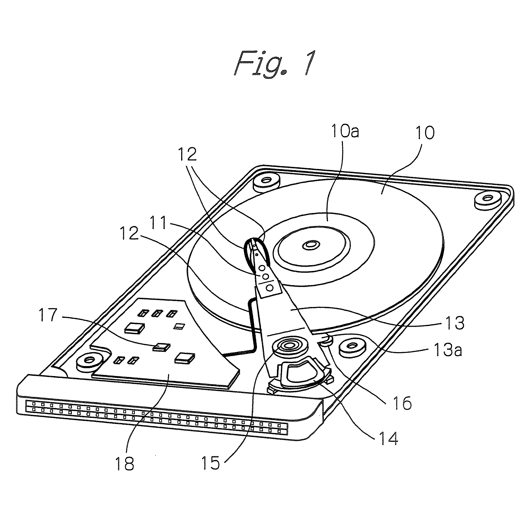
[0057]FIG. 1 schematically illustrates a whole structure of an example of a magnetic disk drive apparatus with an acceleration sensor assembled therein. This magnetic disk drive apparatus is a micro HDD apparatus using at least one magnetic disk of for example 2.5 inches, 1.8 inches, 1.3 inches, or 1.0 or less inches. Such micro HDD apparatus may be an HDD apparatus assembled in mobile equipment such as for example a walkabout personal computer, a mobile phone, a digital audio player or other mobile gear, or an HDD apparatus used itself as a mobile storage or a removable HDD.

[0058]In the figure indicating uncovered state of the magnetic disk drive apparatus, reference numeral 10 denotes a magnetic disk rotated by a spindle motor in operation, and 10a denotes a retracted zone of the magnetic disk 10, with no written data. A magnetic head moves into the retracted zone upon detection of drop of the magnetic disk drive apparatus. In the figure, also, reference numeral 11 denotes a head ...


PUM


Abstract

An acceleration sensor includes a pair of permanent magnets, each having a surface facing a magnetic field detection sensor, arranged in parallel so that the surfaces of the pair of permanent magnets have different magnetic polarities with each other, a spring member for supporting the pair of permanent magnets to displace the pair of permanent magnets when an external force is applied, and a magnetic field detection sensor mounted in stationary state to face the pair of permanent magnets. The magnetic field detection sensor has at least one pair of multi-layered MR elements, each including a magnetization fixed layer and a magnetization free layer, the magnetization fixed layer being magnetized in a direction parallel to a displacement detection direction. The pair of permanent magnets are arranged so that a longitudinal direction of each permanent magnet is in parallel with the magnetized direction of the magnetization fixed layer.

Description

PRIORITY CLAIM[0001]This application claims priority from Japanese patent application No. 2006-032434, filed on Feb. 9, 2006, which is incorporated herein by reference.BACKGROUND OF THE INVENTION[0002]1. Field of the Invention[0003]The present invention relates to an acceleration sensor using multi-layered magnetoresistive effect (MR) elements, which can be utilized for detecting movement of a mobile equipment or for detecting movement of a device or equipment that is supposed to move, and to a magnetic disk drive apparatus with the acceleration sensor.[0004]2. Description of the Related Art[0005]In a magnetic disk drive apparatus or a hard disk drive (HDD) apparatus assembled in a mobile equipment such as for example a walkabout personal computer, a mobile phone, a digital audio player and other mobile gear, an HDD apparatus used as a mobile storage itself or a removable HDD apparatus, in order to prevent a collision of a magnetic head with a hard disk surface due to drop impact, i...

Claims


Application Information

Patent Timeline
IPC IPC(8): G01P15/11
CPCG01P15/105G11B19/04G01P15/18
Inventor SHOJI, SHIGERU
Owner TDK CORPARATION
Learn More