Robotic system with traction drive

a technology of traction drive and robot, which is applied in the direction of mechanical measuring arrangement, instruments, manufacturing tools, etc., can solve the problems of increasing uncertainty in the position of components, the inability to assemble components even with a perfect machine, and the inability to make a perfect machine. , to achieve the effect of eliminating high friction, low cost and high precision component placemen

Inactive Publication Date: 2007-08-16
PRECISE AUTOMATION
View PDF18 Cites 11 Cited by
  • Summary
  • Abstract
  • Description
  • Claims
  • Application Information

AI Technical Summary

Benefits of technology

[0013] A machine vision camera may be mounted such that the camera field of view can see both the component held by the robot, and the placement destination at the same time. For example, the camera may view the component and its placement destination along the placement axis, e.g., through a hole or other opening in a portion of the robotic device. Current assembly machines that incorporate machine vision are designed with cameras offset from the placement axis, such that one or more pictures must be taken, with a machine motion required after the picture is taken. Thus, the placement precision depends on the absolute accuracy of the machine motion. One aspect of the invention eliminate

Problems solved by technology

However, as appreciated by the inventor, this approach to machine design may have at least two fundamental limitations: (1) it is practically impossible to make a perfect machine, and (2) as manufactured or handled components become smaller,

Method used


Image

  • Robotic system with traction drive
  • Robotic system with traction drive
  • Robotic system with traction drive

Examples


Embodiment Construction

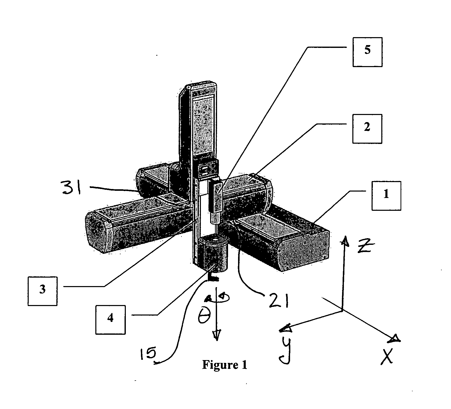
[0026] Various aspects of the invention are described below with reference to illustrative embodiments. However, it should be understood that aspects of the invention are not limited to those embodiments described below, but instead may be used in any suitable system or arrangement. Moreover, aspects of the invention may be used alone or in any suitable combination with other aspects of the invention. For example, a preferred position encoder arrangement is described below in which a unique index code is provided for each set of lines in a count track. It should be understood that this aspect of the invention may be used with a robotic device having a traction drive, machine vision system and / or other features described herein, or may be used in other robotic systems without such features. As another example, a robotic device that incorporates a traction drive and “net-shape” drive surface for the traction wheel in accordance with one aspect of the invention need not also use the pr...


PUM


Abstract

A robotic system including at least one support that supports a carriage for movement. The support may include a drive surface that is a “net shape” surface, i.e., is formed without machining. The carriage may have a traction drive that engages with the drive surface to move the carriage relative to the support. The traction drive may allow for slip at the drive surface. A bearing arrangement used to support the carriage on the support may require mainly radial forces be exerted on roller bearing elements on the carriage. A machine vision system and/or force control techniques may be used to control movement of the carriage and/or other portions of the robotic system.

Description

BACKGROUND [0001] 1. Field of Invention [0002] Aspects of the invention relate to robotic systems, e.g., a Cartesian robot including machine vision, force control, and a traction drive for moving at least one portion of the robot. [0003] 2. Related Art [0004] With the increasing miniaturization of many products and processes, tolerances and quality requirements are approaching the point where people cannot reliably handle material or assemble products without causing damage to or contamination of the material or products. This has increased the demand for automation for handling and assembling small components in many industries, including for example, semiconductor, mass storage, life sciences, laboratory automation, medical products, consumer electronics, automotive, etc. [0005] The cost of automation that is capable of high-tolerance material handling and assembly has increased, largely because of the approach taken by machine manufacturers. Machines have been built with increase...

Claims


Application Information

Patent Timeline
IPC IPC(8): G01B5/004
CPCB25J9/023B25J5/02
Inventor CARLISLE, BRIAN
Owner PRECISE AUTOMATION
Why Eureka
Try Eureka