
Polymer actuator

a technology of actuators and polymers, applied in the direction of generators/motors, mechanical equipment, machines/engines, etc., can solve the problems of large outputs of powerful actuators, heavy weight of actuators, and large weight of actuators

Inactive Publication Date: 2007-08-16
SONY CORP
View PDF3 Cites 13 Cited by
  • Summary
  • Abstract
  • Description
  • Claims
  • Application Information

AI Technical Summary

Benefits of technology

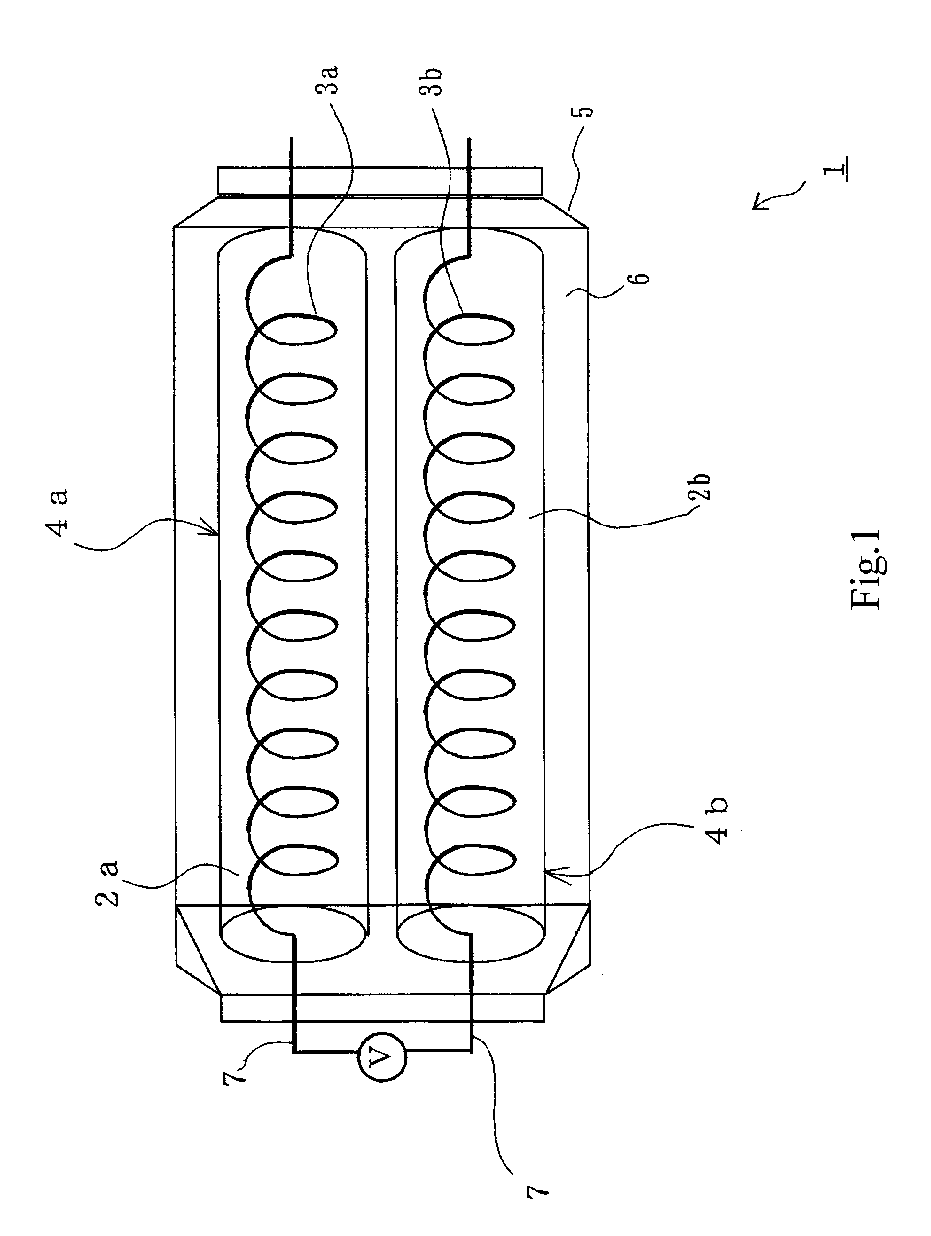
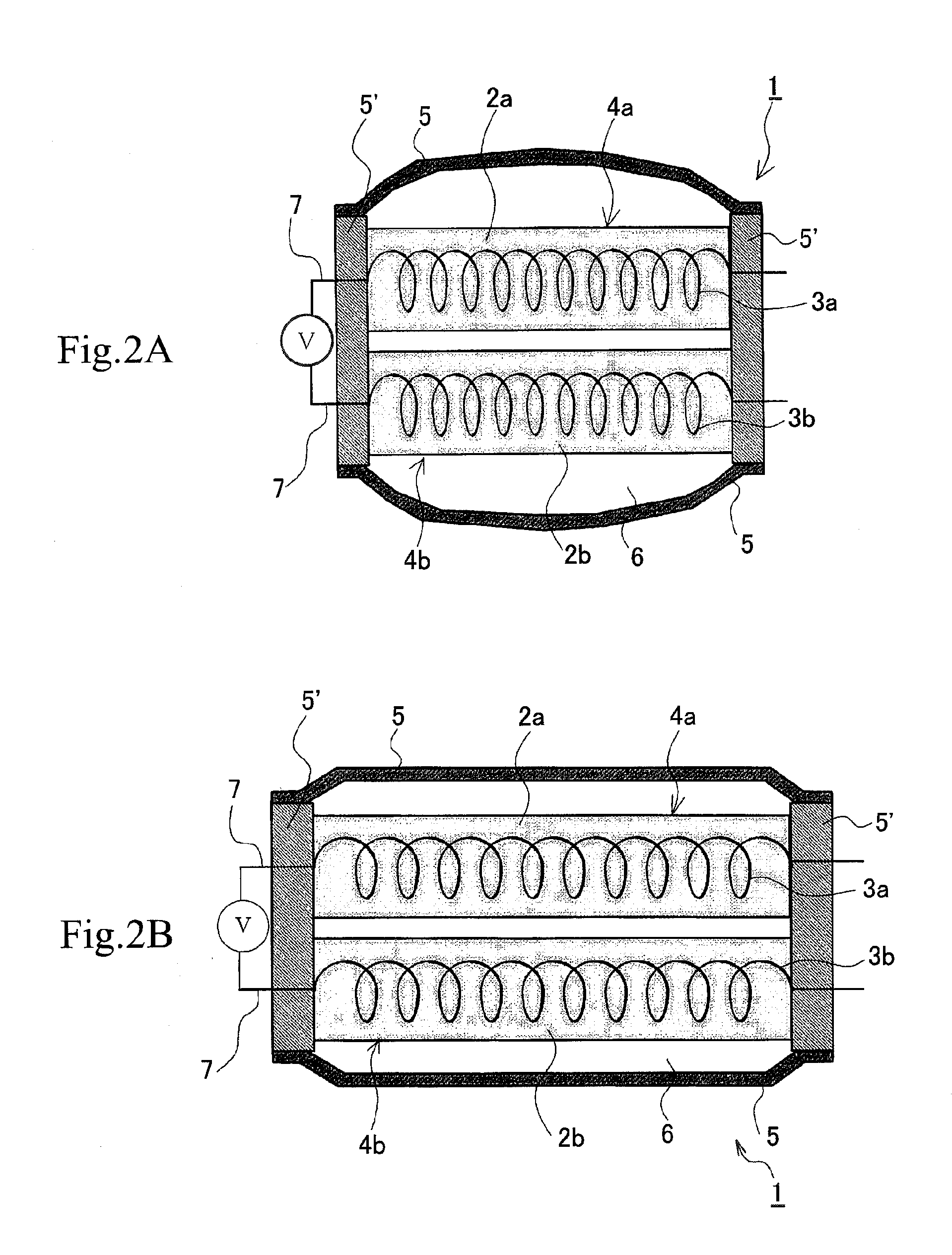
[0022] The present invention is directed to a polymer actuator which comprises a plurality of gel / electrode complexes arranged in an electrolytic aqueous solution, said gel / electrode complex being composed of a polymer gel containing at least either of acidic or basic functional groups and electrodes placed in the polymer gel, said electrodes being made of a material capable of occluding and releasing hydrogen electrochemically, such that the polymer gel in the gel / electrode complex changes in pH upon application of voltage across the electrodes of the gel / electrode complexes and each of the gel / complexes changes in volume in response to the pH change.

Problems solved by technology

This actuator, however, suffers the disadvantage of being heavy because it is made of metal.
Heavy actuator needs large outputs, and powerful actuators are large and heavy.
This is a difficult-to-solve contradictory problem.
Speed reducers deteriorate with time as gears therein wear out.
Ultrasonic motors producing a high torque at a low rotating speed do not need speed reducers; but they are also heavy (and hence poses the same problem as mentioned above) because they are made of metal.
It cannot be heated or cooled rapidly.
Consequently, it is not suitable for small, light systems.
This causes the gel to swell.
This causes the gel to shrink.
This causes the gel to swell.
Unfortunately, the actuator of curved displacement type is hardly applicable to robot articulations unlike the actuator capable of linearly expanding and contracting like skeletal muscles.
However, it is very difficult to fix the gel near one electrode while allowing the gel to expand and contract freely.
Unfortunately, voltage application brings about the electrolysis of water, which decreases the OH— concentration due to oxidation near the anode, thereby lowering the pH and generating oxygen gas, and which also decreases the H+ concentration due to reduction near the cathode, thereby raising the pH and generating hydrogen gas.
The pH change may occur at a place comparatively far from the electrodes when current flowing across the electrodes increases; however, the evolution of oxygen and hydrogen gases and the consumption of water (as a solvent for electrolyte) still pose a problem with designing a closed actuator element.

Method used


Image

  • Polymer actuator
  • Polymer actuator
  • Polymer actuator

Examples


example 1

[0069] In this example, the polymeric hydrogel for the gel / electrode complexes is prepared from an aqueous solution of monomer, crosslinking agent, and initiator by radical polymerization.

[0070] The monomer for the polymer having acidic functional groups is sodium acrylate. The crosslinking agent is N,N′-methylenebisacrylamide. The initiator is ammonium persulfate. The aqueous solutions (as the gel precursor) is composed of the monomer, crosslinking agent, and initiator in a molar ratio of 100:3:1.

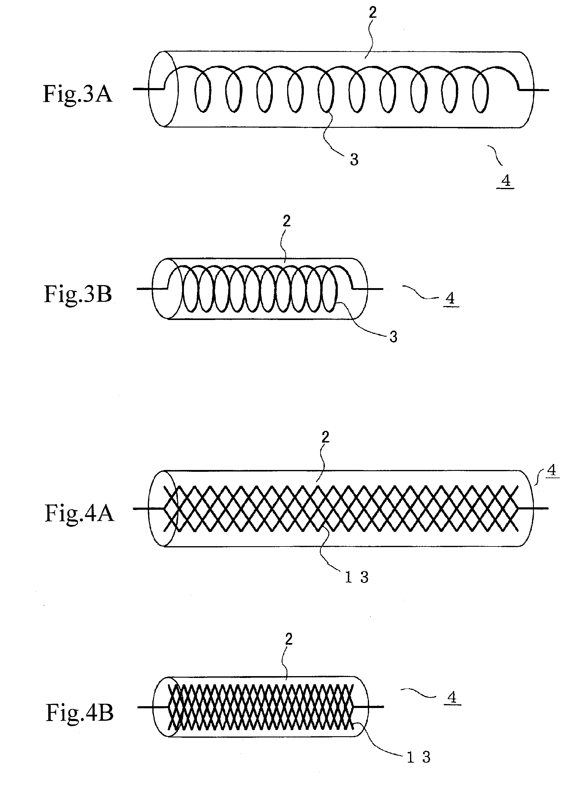
[0071] The electrode is a coil (1 mm in diameter) of platinum wire (10 μm in diameter). It is placed in a glass tube, 1.5 mm in inside diameter and 30 mm long, and then it is fixed so that the axis of the coil coincides with the axis of the glass tube.

[0072] The glass tube is filled with the gel precursor solution. With its both ends closed by rubber stoppers, the filled glass tube is heated at 50° C. so that the gel precursor solution undergoes gelation. The resulting gel is discharged...

example 2

[0081] In this example, the polymeric hydrogel for the gel / electrode complexes is prepared from an aqueous solution of monomer, crosslinking agent, and initiator by radical polymerization.

[0082] The monomer for the polymer having acidic functional groups is acrylic acid. The monomer for the polymer having basic functional groups is dimethylaminoethyl methacrylate. The crosslinking agent is N,N′-methylenebisarcylamide. The initiator is ammonium persulfate. The aqueous solution (as the gel precursor) is composed of the acidic monomer, basic monomer, crosslinking agent, and initiator in a molar ratio of 50:50:3:1.

[0083] The electrode is a coil (1 mm in diameter) of platinum wire (10 μm in diameter). It is placed in a glass tube, 1.5 mm in inside diameter and 30 mm long, and then it is fixed so that the axis of the coil coincides with the axis of the glass tube.

[0084] The glass tube is filled with the gel precursor solution. With its both ends closed by rubber stoppers, the filled gl...

example 3

[0090] The same procedure as in Example 1 was repeated to prepare the polymer actuator except that the gel precursor solution was incorporated with as much Pd powder as 10 wt % of the monomer.

[0091] The resulting polymer actuator was tested by applying a voltage of 2 V across the acidic gel / electrode complex (as an anode) and the basic gel / electrode complex (as a cathode). It was found that polymer actuator decreased in length between the heat-sealed parts from 45 mm to 31 mm as the result of contraction of both of the gel / electrode complexes. During contraction, no gas evolution from the gel / electrode complex was noticed.


PUM


Abstract

To provide a polymer actuator which is light in weight and capable of linear expansion and contraction with a low voltage. The polymer actuator 1 is composed of a plurality of gel / electrode complexes arranged in an electrolytic aqueous solution 6, said gel / electrode complex being composed of a polymer gel (2a, 2b) containing at least either of acidic or basic functional groups and electrodes (3a, 3b) placed in the polymer gel, said electrodes being made of a material capable of occluding and releasing hydrogen electrochemically, such that the polymer gel (2a, 2b) in the gel / electrode complex changes in pH upon application of voltage across the electrodes (3a, 3b) of the gel / electrode complexes (4a, 4b) and each of the gel / complexes changes in volume in response to the pH change.

Description

TECHNICAL FIELD [0001] The present invention relates to a polymer actuator. BACKGROUND ART [0002] The usefulness of robots is attracting attention in various fields including nursing care service, dangerous work, and entertainment. Robots suitable for these uses are required to have articulations (movable parts) similar to those of animals that permit complex movements. [0003] A conventional actuator to drive these movable parts is a magnetic rotary motor. This actuator, however, suffers the disadvantage of being heavy because it is made of metal. [0004] Weight of actuators built into movable parts add to loads. Heavy actuator needs large outputs, and powerful actuators are large and heavy. This is a difficult-to-solve contradictory problem. [0005] Moreover, magnetic rotary motors require speed reducers to control rotating speed and torque. Speed reducers deteriorate with time as gears therein wear out. [0006] Ultrasonic motors producing a high torque at a low rotating speed do not ...

Claims


Application Information

Patent Timeline
IPC IPC(8): A61K9/00F03G7/00H02N11/00
CPCF03G7/005Y10S310/80H02N11/00
Inventor ITO, HIDETOSHIKEZUKA, KOICHIRO
Owner SONY CORP
Learn More