Controlled-release vapor fuel cell

a vapor fuel cell, controlled technology, applied in the direction of cell components, electrochemical generators, cell component details, etc., can solve the problems of difficult and expensive fabrication and assembly, and achieve the effects of low fuel utilization, high fuel cross-over problems, and reduced methanol crossover

Active Publication Date: 2007-08-16
NANOTEK INSTR GRP LLC
View PDF7 Cites 25 Cited by
  • Summary
  • Abstract
  • Description
  • Claims
  • Application Information

AI Technical Summary

Benefits of technology

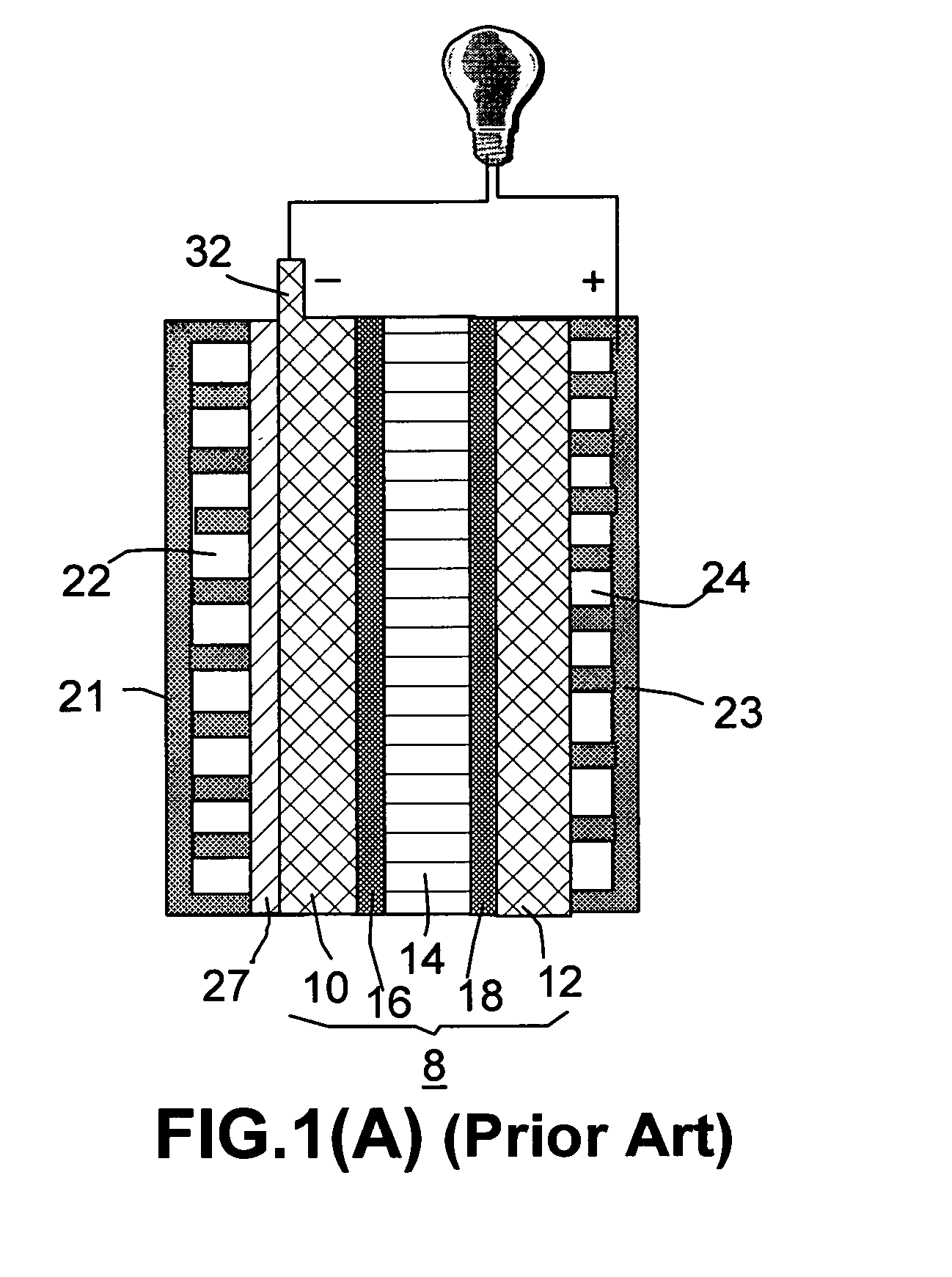
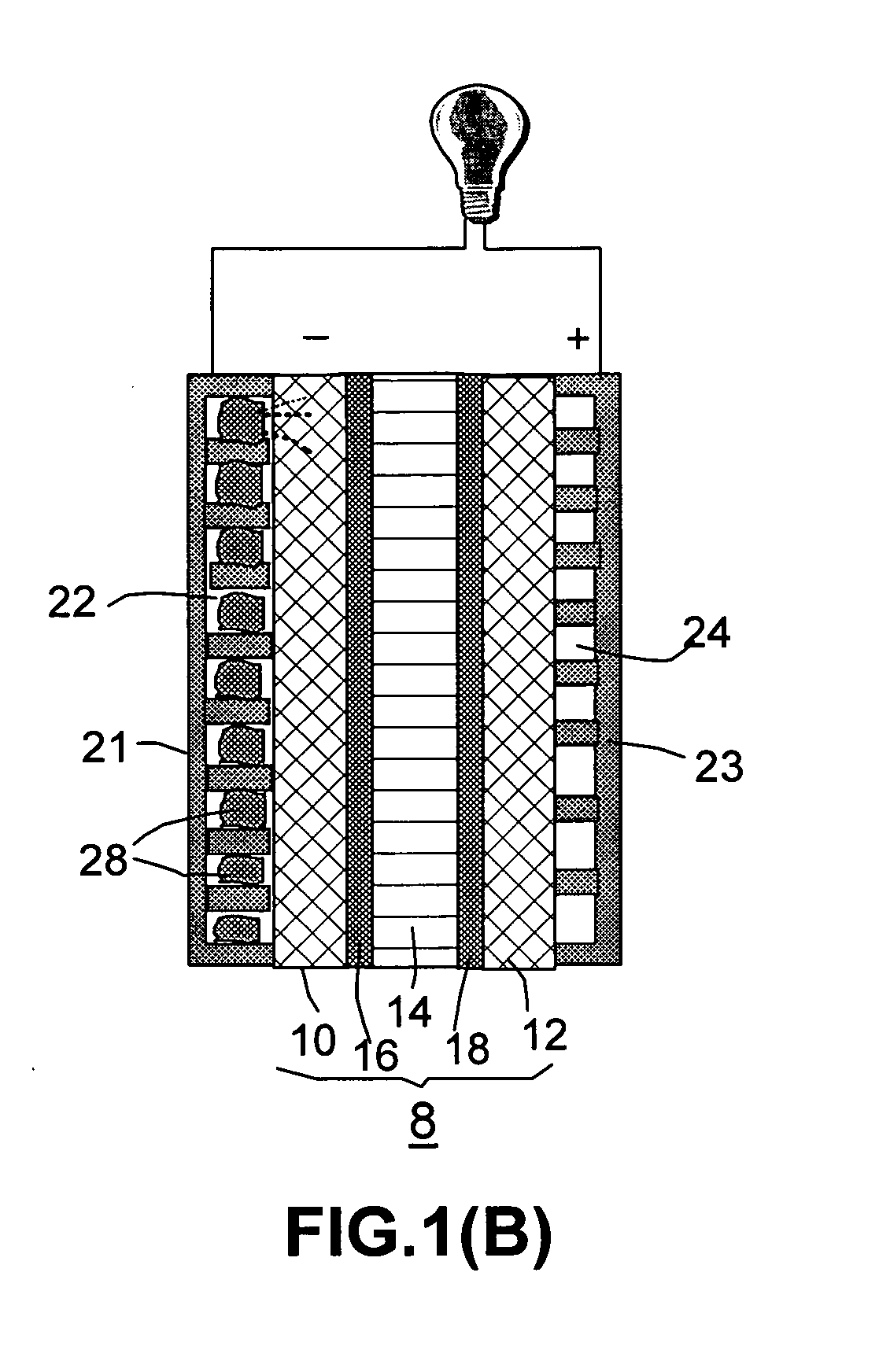
[0022] The present invention provides a light-weight, compact fuel cell that is well-suited to powering portable electronic devices and vehicles, particularly light-duty vehicles such as golf carts, forklifts, wheelchairs, motor bikes, and scooters. The fuel cell comprises the following major components: (a) a membrane electrode assembly, comprising (i) a proton exchange membrane (PEM) sandwiched between (ii) an anode (typically comprising an anode backing layer and an anode electro-catalyst layer) and (iii) a cathode (typically comprising a cathode backing layer and electro-catalyst); (b) a fuel flow field plate having surface channels positioned in front of the anode with the channels containing therein a controlled-release material that absorbs and substantially retains a liquid fuel at or below an ambient temperature, but releases the fuel at a temperature higher than an activation temperature to deliver a fuel vapor to the anode at a desired rate; (c) heating means in heat-supplying relation to the controlled-release material to activate fuel vapor release on demand; and (d) fuel supplier to accommodate and feed the organic fuel and water, separately or as a mixture, to the controlled release material.
[0023] A special feature of the presently invented fuel cell is that the fuel (e.g., methanol and water) is supplied initially in a liquid form into the anode compartment. To accomplish this function, the fuel flow channels of a flow field plate comprise therein a controlled-release material being in fluid communication with a liquid fuel source and receiving the liquid fuel therefrom. Specifically, this controlled-release material absorbs liquid fuel and possibly gets swollen to a controlled extent to retain a desired amount of liquid fuel. When the fuel cell is not in operation, this amount of fuel is substantially retained without a parasitic loss at room temperature or below an ambient temperature. When the fuel cell is in operation, heat is supplied to activate the vapor release process, allowing the fuel vapor transport to the anode catalyst phase at a well-controlled rate. The vaporous fuel is oxidized at a higher temperature in a more efficient manner with much reduced methanol crossover. The needed heat may come partially from the electrochemical reactions occurring at the electrodes. Additional heat comes from a heating element positioned near the controlled-release material. During the start-up in real practice, an attendant battery (preferably a rechargeable one) or other small energy source may be operated to energize the heating element that generates the initial amount of heat sufficient to activate the vapor releasing procedure to trigger the operation of the fuel cell. Once the fuel cell begins to operate, it will generate more than enough electricity to not only power the external load but also recharge the battery. Since the electrochemical reactions proceed so efficiently, the amount of power needed to energize the heating element and recharge the battery represents but a very small fraction of the power that can be generated by the invented fuel cell.
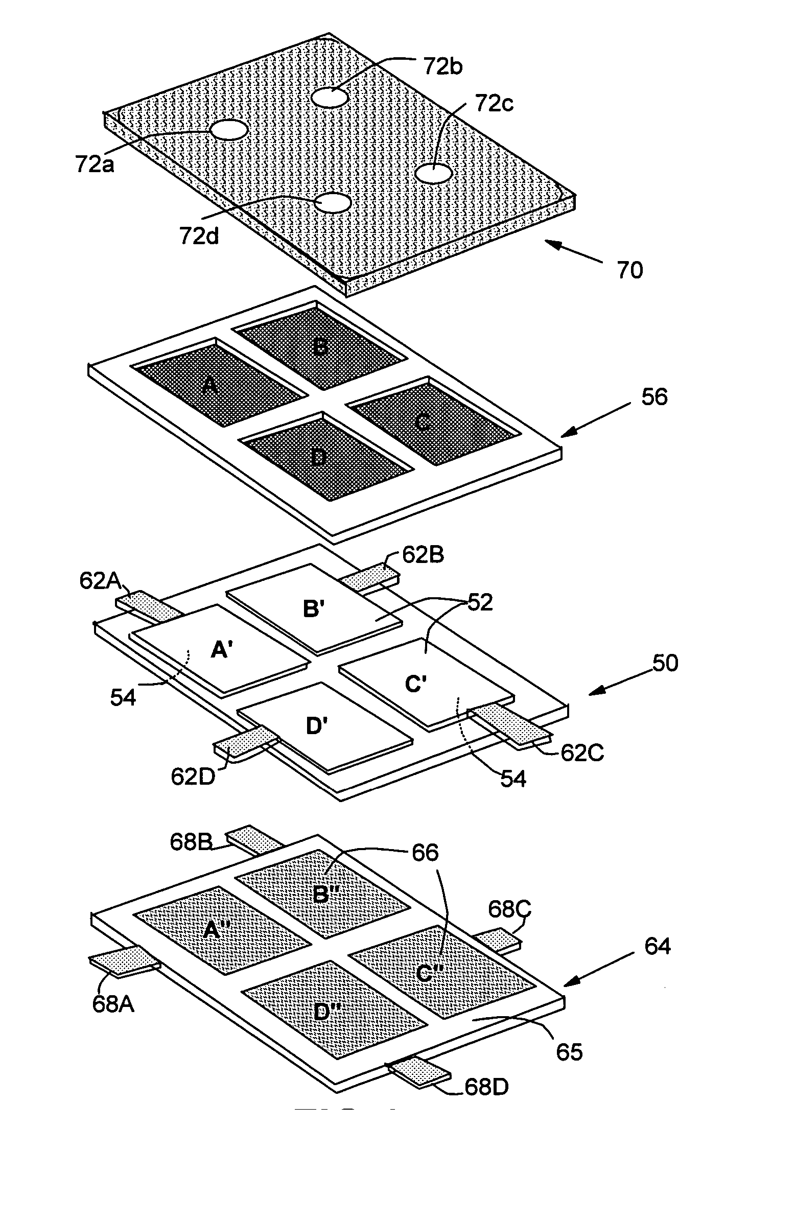
[0024] Another preferred embodiment of the present invention is a planar fuel cell, comprising: (a) a membrane electrode assembly, comprising one solid electrolyte sheet (or several individual solid electrolyte sheets substantially on the same plane) having a plurality of anodes disposed on only one major side of the solid electrolyte sheet and a plurality of corresponding cathodes disposed on only an opposing major side of the solid electrolyte sheet; (b) a fuel flow field plate positioned in front of the anodes, with this plate containing a controlled-release material in surface flow channels of this plate and facing the anode direction. These channels are in fluid communication with a fuel supply system which feeds liquid fuel to the controlled-release material. This controlled-release material absorbs a controlled amount of liquid organic fuel and / or water and retains this amount at or below an ambient temperature. This material emits vapors of organic fuel and / or water at a temperature higher than an activation temperature to deliver a fuel vapor to the anodes; (c) heating means in heat-supplying relation to the controlled-release material to activate fuel vapor emission on demand; (d) fuel supply means (the fuel supply system) to deliver the organic fuel and water to the controlled-release material; and (e) a plurality of current collectors each having an interconnect means, wherein each of the plurality of anodes and each of the plurality of cathodes has one of the plurality of current collectors associated therewith and the interconnect means are arranged to provide electron transfer between anodes and cathodes.
[0025] This planar fuel cell system overcomes several shortcomings of prior art fuel cell stacks. For instance, the need to stack several unit fuel cells together normally requires complex flat stack arrangements and involves numerous parts (gaskets, channels, and bipolar plates, etc.) that may be difficult and expensive to fabricate and assemble. Traditional planar fuel cell stacks based on direct methanol fuel cell units also suffer from low fuel utilization and high fuel cross-over problems, which are overcome by the present invention.

Problems solved by technology

For instance, the need to stack several unit fuel cells together normally requires complex flat stack arrangements and involves numerous parts (gaskets, channels, and bipolar plates, etc.) that may be difficult and expensive to fabricate and assemble.

Method used


Image

  • Controlled-release vapor fuel cell
  • Controlled-release vapor fuel cell
  • Controlled-release vapor fuel cell

Examples


example 1

Polyurethane-Based Controlled-Release Material

[0078] Polyurethane (PU) was prepared by the reaction of toluene-2,4-diisocyanate with hydroxy-terminated oligomers. Oligomers were either liquid polybutadiene (MW 3000) or propylene oxide-based polyethers (MW 420 and 4800). Polyurethanes with linking segments formed predominantly by high-molecular-weight oligomers (MW 3000 or 4800) were rubbery materials with a glass transition temperature (Tg) lower than room temperature. By contrast, hard glassy membranes (Tg>room temperature) were obtained if the linking segments comprised high amounts of a polyether with MW 420. When a fuel mixture of water and methanol was fed to a glassy PU material (with or without pores, the latter being like in a foam or sponge), the fuel liquid is absorbed and retained at a TTg, all glassy PU materials allowed for evaporation of methanol at reasonable rates. In the cases of rubbery PU materials, minimal evaporation occurs at room temperature, but significant ...

example 2

Poly (Vinyl Alcohol)-Based Controlled-Release Material

[0079] Poly (vinyl alcohol) (PVA) can be modified to obtain phosphatic anionic PVA (P-PVA) and quaternary ammonium cationic PVA (C-PVA) with various degrees of substitution (D.S.). The polyelectrolyte complex membrane prepared by mixing P-PVA (D.S.=2.3%) and C-PVA (D.S.=2.9%) with weight ratio of 1 / 1, showed a good evaporation rate at 75° C. or above. Additionally, cross-linked PVA material was prepared with poly (acrylic acid-co-maleic anhydride) (PAAM) serving as a polymeric cross-linking agent. Cross-linked materials were characterized by good water and methanol swelling and evaporation capabilities. Swelling ratio decreased with increasing cross-linking agent content since the swelling of water molecule is restricted by chemical cross-linking between PVA chains and polymeric cross-linking agent chains and physical cross-linking by entanglement between the chains. When the contents of cross-linking agent increased, evaporatio...

example 3

Methanol Selective Controlled-Release Materials

[0081] Polymeric membranes with excellent chemical resistance were prepared from polar polymers including NBR (Acrylonitrile-Butadiene Rubber) and Poly (vinyl chloride). These materials were cross-linked to form chemically and mechanically robust materials, which were all more capable of emitting methanol than water vapors. The permeation rates were negligible at room temperature, but become appreciable at 60° C. or higher.

[0082] The evaporation performance of polymer blends made from cellulose acetate and cellulose acetate hydrogen phthalate were also studied. All the tested material compositions were found to evaporate methanol preferentially. The selectivity increases and the evaporation rate decreases with increasing cellulose acetate content in the blend. When the feed temperature or the methanol content in the feed increases, the evaporation rates of a material with a 30 wt % in cellulose acetate are greatly enhanced and the sel...


PUM

PropertyMeasurementUnit
temperaturesaaaaaaaaaa
boiling temperaturesaaaaaaaaaa

Abstract

A controlled-release fuel cell comprising (a) a proton exchange membrane having a first surface and a second surface, a fuel electrode or anode being coupled to the first surface, and an oxidant electrode or cathode being coupled to the second surface; (b) a fuel flow field plate having surface channels positioned in front of the anode with the channels containing therein a controlled-release material that retains a liquid fuel at or below an ambient temperature, but releases the fuel at a temperature higher than an activation temperature to deliver a fuel vapor to the anode; (c) heating means in heat-supplying relation to the controlled-release material to activate fuel vapor release on demand at a desired rate; and (d) fuel supply means that feeds the liquid fuel to the controlled-release material. The invented fuel cell is compact and lightweight, with significantly reduced fuel crossover and improved fuel utilization efficiency. The fuel cell is particularly useful for powering small vehicles and portable devices such as a notebook computer, a personal digital assistant, a mobile phone, and a digital camera.

Description

[0001] This invention is a result of a research project supported in part by the NSF SBIR-STTR program. FIELD OF THE INVENTION [0002] This invention relates to an organic vapor fuel cell (OVFC) operating on a hydrogen-rich organic or hydrocarbon fuel that is fed into the fuel cell initially in a liquid form, but is converted into a vapor form prior to coming in contact with the anode electro-catalyst phase. The invention specifically relates to fuel cells such as the direct methanol fuel cell (DMFC) and the direct ethanol vapor fuel cell (DEFC) that are operated at relatively high temperatures (e.g., 80-160° C. for DMFC). BACKGROUND OF THE INVENTION [0003] A fuel cell converts the chemical energy into electricity. A fuel cell differs from a battery in that the fuel and oxidant of a fuel cell are supplied from sources that are external to the cell, which can generate power as long as the fuel and oxidant are supplied. A particularly useful fuel cell for powering portable electronic d...

Claims


Application Information

Patent Timeline
Patent Type & Authority Applications(United States)
IPC IPC(8): H01M8/04H01M8/02
CPCH01M8/0258H01M8/04186H01M8/04201H01M8/1009Y02E60/522H01M8/1013H01M8/249Y02E60/523H01M8/1011H01M8/0267Y02E60/50
Inventor SONG, LULUGUO, JIUSHENGZHAMU, ARUNAJANG, BOR Z.
Owner NANOTEK INSTR GRP LLC
Why Eureka
Try Eureka