Laser system
a laser system and laser technology, applied in the field of lasers, can solve the problems of inability to accurately align, difficult to cost-effectively fabricate, and difficult to discharge lasers with sufficient accuracy, and achieve the effects of increasing laser power and/or efficiency, accurate alignment, and low degradation
Active Publication Date: 2007-08-23
VIDEOJET TECH INC
View PDF66 Cites 39 Cited by
- Summary
- Abstract
- Description
- Claims
- Application Information
AI Technical Summary
Benefits of technology
The present invention provides methods and devices for the construction of gaseous lasers. It includes the use of ceramic portions in the formation of laser discharge chambers, the use of protrusions in the formation of laser discharge structures, and the combination of protrusions with ceramic portions. The invention also discusses optimizing electrode spacing to increase laser power and efficiency. Additionally, it describes the use of diffraction gratings for wavelength selection and the use of multiple and single lasers. The invention also includes methods of discharge partitioning and the use of reflective means for wavelength selection. The patent text provides a detailed description of the invention and its applications.
Problems solved by technology
Discharge lasers suffer from the disadvantage that, for the lengths needed, the discharges are difficult to fabricate with sufficient accuracy at a reasonable cost to obtain acceptable laser performance.
It is very difficult to cost-effectively fabricate a typical discharge structure that is roughly 30 to 40 cm long with a 1.5 to 3.0 mm bore.
Bore cross-section inaccuracy leads to unacceptable laser transverse mode characteristics and reduced power output.
With Al2O3, thermal efficiency requirements dictate the use of a large ceramic area, which creates a lossy RF circuit.
Ideally materials with good thermal properties such as BeO and AlN are desirable as the ceramic, but are prohibitively expensive with related art discharge designs.
Additionally the resonator cavities of discharge lasers suffer energy losses from misalignment of the containment mirrors, impingement of laser with the discharge walls, and reflectivity properties of the containment.
Thermal heating in high powered lasers can distort the reflectivity properties resulting in laser degradation.
For example, the use of curved containment mirrors results in variable beam radius throughout the resonator cavity, thus the discharge channels of related art fail to allow the optimization of the discharge with respect to variable beam radius in the resonator channel.
Various spacing between electrodes results in varying power levels and current.
Current related art fails to fully optimize the electrode spacing and instead conventional methods focus on ease of manufacturing instead of optical optimization since a portion of the spacing is filled with the ceramic discharge structure.
Additional problems exist in conventional gaseous lasers, for example, laser startup.
The problem with the optical maneuvered missiles is that they are extremely hard to launch and steer so the missile hit rate drops significantly.
Initially CO2 gas lasers were built that emit infrared energy at the correct wavelength to be added to the spinning wheel detector's input to cause a signal that the missile misreads, which causes the missile to veer off or explode prematurely because of the errant infrared signal.
The YAG lasers can only jam the missiles detectors so they are useless against both the British / Swede type of design and are also useless against the new focal plane array detector technology.
Problems exist in scaling up low power rf-excited gas discharge lasers to high power ones.
The rf power distribution tends to become uneven over the discharge area and instead concentrates in one spot, thereby ruining what should otherwise have been a uniformly excited discharge suitable for efficient laser power extraction.
Area scaling of dc-excited CO2 lasers can be problematic because of the tendency of the dc discharge to filament into a “lightning bolt” arc.
This can increase the likelihood of the gamma discharge recurrence and its transition to an arc, especially during discharge initiation (“striking”).
Method used
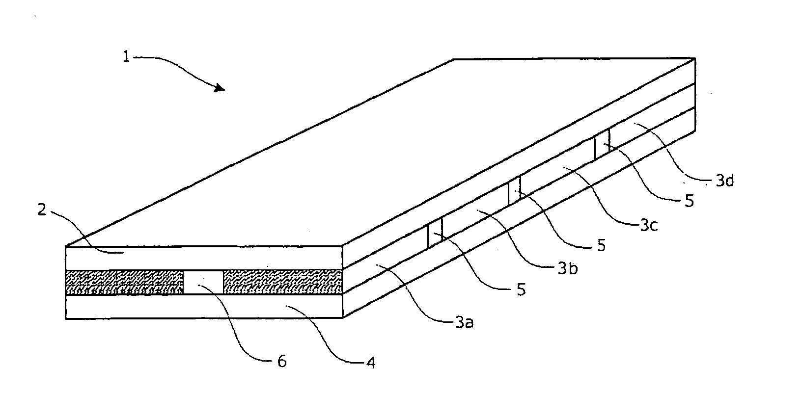
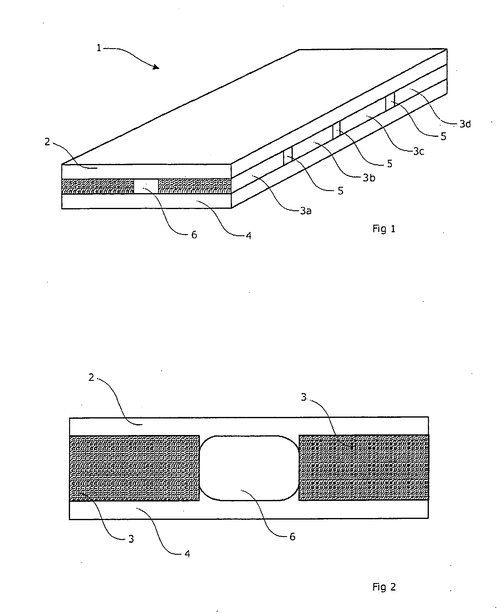
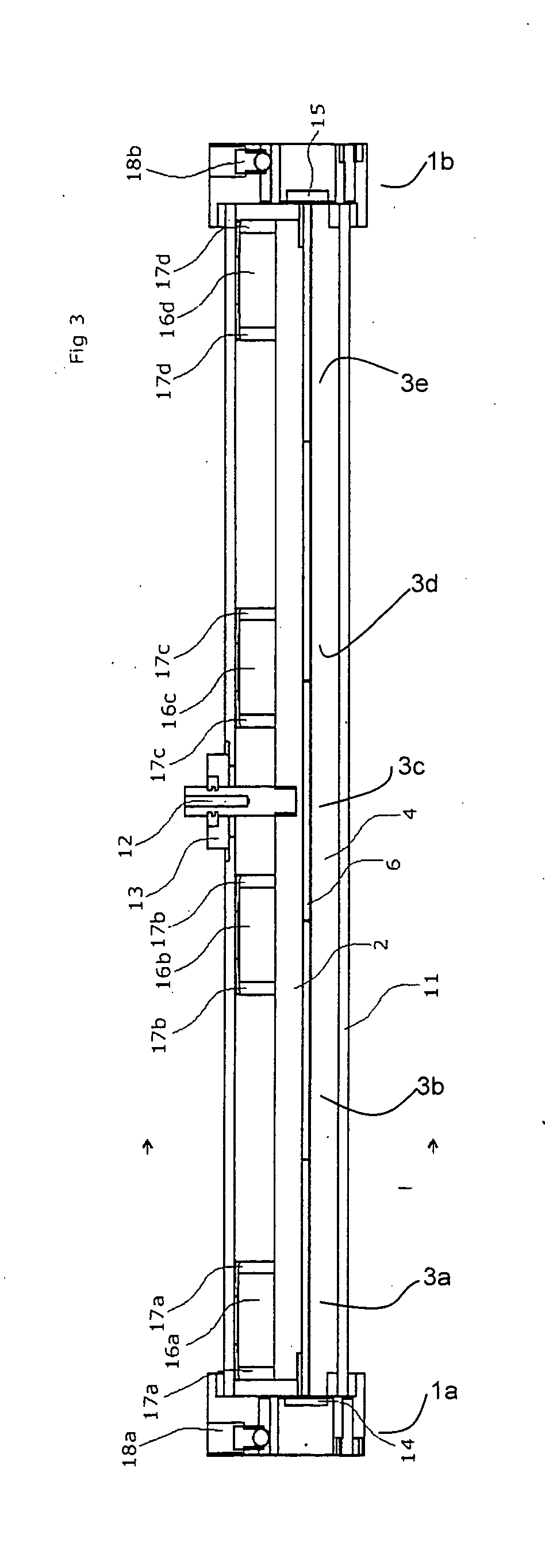
View moreImage
Smart ImageViewing Examples

Examples
example 1
[0126] Eo=8.89 pF / m, Ere=1 for CO2 gas mix, Le=36″(914.4 mm), We=4.5″(114.3 mm), de=1.75 mm [0127] Ce=531 pF [0128] The capacitance between pad and it's electrode Cp is:
Cp=EoErpLpWp / dp (2)
example 2
[0129] Erp=9 for alumina ceramic, Lp=2.210″(56.1 mm), Wp=1.712″(43.5 mm), dp=0.030″(0.75 mm), [0130] Cp=260 pF [0131] The capacitance between a pad and the pad opposing it (“inter-pad”) across the electrode gap on the opposite electrode Cpp is:
Cpp=EoEreLpWp / de (3)
example 3
[0132] Cpp=12.4 pF [0133] With a strap inductance L in parallel with each pad capacitance the reactance at rf frequency f between pad and it's electrode is:
Xp=1 / wCp, no strap inductance (4a)
Xp=wL / (1−w2LCp), where w=2 pi f (4b)
Login to View More PUM
 Abstract
A laser discharge, where the laser discharge can be formed by electrodes and at least one sidewall in a manner allowing a more compact structure than previously provided. Protrusions in the electrodes allow easier laser starts, and sectional sidewall(s) allow easier fabrication of sidewall(s), decreasing manufacturing costs.
Description
FIELD OF THE INVENTION [0001] The invention relates in general to lasers and particularly but not exclusively to RF excited lasers. BACKGROUND OF THE INVENTION [0002] A discharge laser typically consists of two mirrors, concave or flat, defining an optical resonator cavity coupled together with a discharge defining an optical path between the reflectors. [0003] The discharge is typically a channel ground into a ceramic block (e.g. aluminum oxide, Al2O3) with a lower electrode of aluminum or copper added to complete a cross-section of the discharge. Alternatively, the discharge can be ultrasonically drilled down through a piece of ceramic such as aluminum oxide (Al2O3) to create a continuous closed bore length with upper and lower electrodes parallel to the bore length. Typically, the positive arm of the oscillating electromagnetic field (e.g. Radio Frequency—RF) supply will be coupled into the upper electrode of the discharge, and the ground plane of the RF supply will be coupled to...
Claims
Login to View More Application Information
Patent Timeline
 Patent Type & Authority Applications(United States)
IPC IPC(8): H01S3/00
CPCH01S3/0315H01S3/036H01S3/0385H01S3/0388H01S3/2232H01S3/076H01S3/0804H01S3/0971H01S3/0975H01S3/073
Inventor MONTY, NATHAN P.LIND, KENNETH A.
Owner VIDEOJET TECH INC