Bond coat process for thermal barrier coating

a technology of thermal barrier coating and bonding layer, which is applied in the direction of superimposed coating process, machines/engines, transportation and packaging, etc., can solve the problems of high temperature durability of engine components, corresponding increase in durability, and insufficient mechanical properties, etc., to improve the coating structure and improve the coating structure

Inactive Publication Date: 2007-09-06
GENERAL ELECTRIC CO
View PDF14 Cites 8 Cited by
  • Summary
  • Abstract
  • Description
  • Claims
  • Application Information

AI Technical Summary

Benefits of technology

[0006] In another embodiment, the present invention is directed to a method for forming a protective bond coating on a substrate. The method comprises the steps of providing an article substrate having a substrate surface, forming a bond coat on the substrate by depositing a beta-phase Ni—Al bond coat by cathodic arc deposition, processing the bond coat by peening to improve the coating structure, and heat treating the bond coat to a preselected temperature for a preselected period of time in a vacuum.
[0007] In another embodiment, the present invention is directed to a method for forming a thermal barrier coating system. The method comprises the steps of providing a nickel-base superalloy article substrate comprising a component of a gas turbine engine and having a substrate surface, forming a bond coat on the substrate by depositing a NiAlCrZr layer by cathodic arc deposition, processing the bond coat by peening to improve the coating structure, heat treating the bond coat in a vacuum at a temperature of from about 1975° F. to about 2000° F. for a duration of from about 2 hours to about 4 hours, and depositing a ceramic thermal barrier coating overlying the bond coat surface.

Problems solved by technology

However, as operating temperatures increase, the high temperature durability of the components of the engine must correspondingly increase.
Nonetheless, when used to form components of the turbine, combustor and augmentor sections of a gas turbine engine, such alloys alone are often susceptible to damage by oxidation and hot corrosion attack and may not retain adequate mechanical properties.
The latter requirement is particularly demanding due to the different coefficients of thermal expansion between ceramic topcoat materials and the superalloy substrates they protect.

Method used


Image

  • Bond coat process for thermal barrier coating
  • Bond coat process for thermal barrier coating
  • Bond coat process for thermal barrier coating

Examples


example

[0030] The following example is given solely for the purpose of illustration and is not to be construed as limitations of embodiments of the present invention, as many variations of the invention, as many variations of the invention are possible without departing from the spirit and scope of embodiments of the invention.

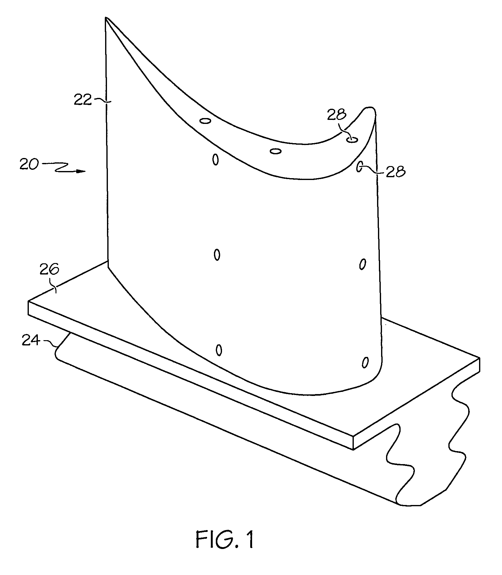
[0031] In the example, the test samples are turbine blades made from a nickel-base superalloy, available by the trade name Rene N5.

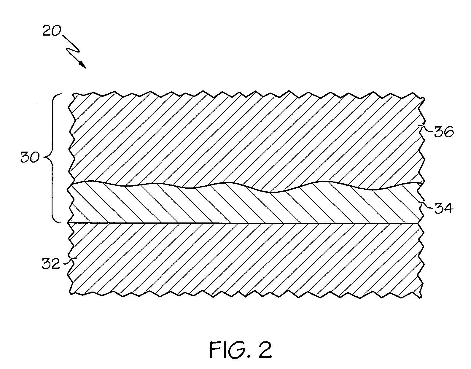
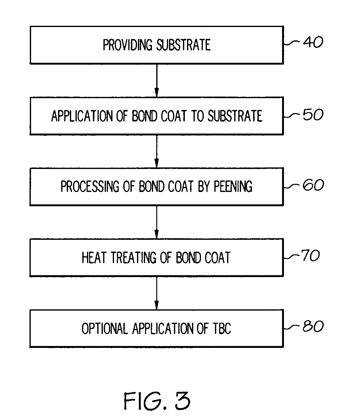
[0032] A process of one embodiment of the invention is used to form a protective bond coating by cathodic arc deposition on test samples as shown in FIG. 4 (“Sample A”) and FIG. 5 (“Sample B”). The bond coat has the following composition: 30 weight percent aluminum, 6 weight percent chromium, 1 weight percent zirconium, and the balance nickel. The bond coat formed has a thickness of 33 microns. Following deposition, Sample B is peened with Z850 ceramic media at an intensity of 12N, 600% coverage. Thereafter, the bond coat is heated to a...


PUM

PropertyMeasurementUnit
thicknessaaaaaaaaaa
temperatureaaaaaaaaaa
thicknessaaaaaaaaaa

Abstract

Methods provide for depositing a bond coat of a thermal barrier coating (TBC) system for a component designed for use in a hostile thermal environment. The method includes providing an article substrate having a substrate surface, forming a bond coat on the substrate by depositing a beta-phase Ni—Al bond coat by cathodic arc deposition, processing the bond coat by peening to improve the coating structure, and heat treating the bond coat. Also disclosed is a turbine blade comprising a nickel-base superalloy substrate, a bond coat on the surface of the substrate, and a ceramic thermal barrier coating overlying the bond coat surface.

Description

TECHNICAL FIELD [0001] The present application relates generally to a process for applying coatings of the type used to protect components exposed to high temperature environments, such as bond coats for protecting the surface of nickel-base superalloys. The present application also relates to forming a protective coating by depositing a Ni—Al based bond coat by cathodic arc deposition on the surface of an aircraft engine component. Another aspect of the present application relates to a coated turbine blade. BACKGROUND OF THE INVENTION [0002] Higher operating temperatures for gas turbine engines are continuously sought in order to increase their efficiency. However, as operating temperatures increase, the high temperature durability of the components of the engine must correspondingly increase. Significant advances in high-temperature capabilities have been achieved through the formulation of nickel- and cobalt-base superalloys. Nonetheless, when used to form components of the turbi...

Claims


Application Information

Patent Timeline
Patent Type & Authority Applications(United States)
IPC IPC(8): C23C14/00B32B15/01
CPCY02T50/67Y10T428/12944Y02T50/676C23C4/18C23C14/16C23C14/5886C23C26/00F01D5/186F01D5/288C23C28/321C23C28/325C23C28/345C23C28/3455F05D2230/313F05D2300/21F05D2230/90F05D2300/15F05D2300/611F05D2300/134Y02T50/671Y02T50/60
Inventor ZIMMERMAN, ROBERT GEORGE JR.EVANS, JOHN DOUGLASVIGUIE, RUDOLFO
Owner GENERAL ELECTRIC CO
Why Eureka
Try Eureka