Energy conversion system for hydrogen generation and uses thereof

Inactive Publication Date: 2007-09-13
RUTLEDGE KEITH
View PDF15 Cites 26 Cited by
  • Summary
  • Abstract
  • Description
  • Claims
  • Application Information

AI Technical Summary

Benefits of technology

[0010] The use of hydrogen, when combined with conventional fossil fuels (e.g. gasoline), is capable of extending the lean limit of such conventional fuels in order to achieve higher efficiency and lower pollutant emissions in a conventional internal combus

Problems solved by technology

During recent decades, it has been recognized that the growing abundance of commercial and passenger vehicles (e.g. which principally employ internal combustion engines) is resulting in a rapid depletion of earth's natural, unrenewable resources (e.g. fossil fuels).
Moreover, the incredible volumes of exhaust gases which are emitted during the world's vehicle operations are causing detrimental changes to the earth's environment.
However, such systems have numerous drawbacks including, for example, that a load is placed on the vehicle's engine and battery charging system to power the electrolysis cell, and that hydrogen gas is only generated when the vehicle is operating and is used without being stored.
Because hydrogen is only generated when the vehi

Method used


Image

  • Energy conversion system for hydrogen generation and uses thereof
  • Energy conversion system for hydrogen generation and uses thereof
  • Energy conversion system for hydrogen generation and uses thereof

Examples


example 1

General H-Brake Operation in an Internal Combustion Engine Vehicle

[0055] An H-Brake is provided as a retrofit kit and installed on-board an internal combustion engine vehicle. The kit includes computerized brake and liquid / gas mixing control members, an electrolyzer, a water / hydrogen storage tank, conduits for supplying water to the electrolyzer and hydrogen to the storage tank and to the liquid / gas mixing control, and a means for coupling a generator / alternator to the drive shaft. Once the vehicle is in motion, the operator depresses the vehicle's foot brake which causes an increase in the alternator's field and thus results in back pressure on the drive train, resulting in slowing / stopping of the vehicle. Concurrently, the vehicle's inertial / kinetic energy is converted to electricity by the generator / alternator.

[0056] The electricity produced by the generator / alternator is then provided to an electrolyzer which utilizes a standard electrolytic solution such as potassium hydroxid...

example 2

H-Brake Kinetic / Inertial Energy Conversion, Storage and Fuel Mixture Control Kit: Drive Shaft Mounted Generator / Alternator

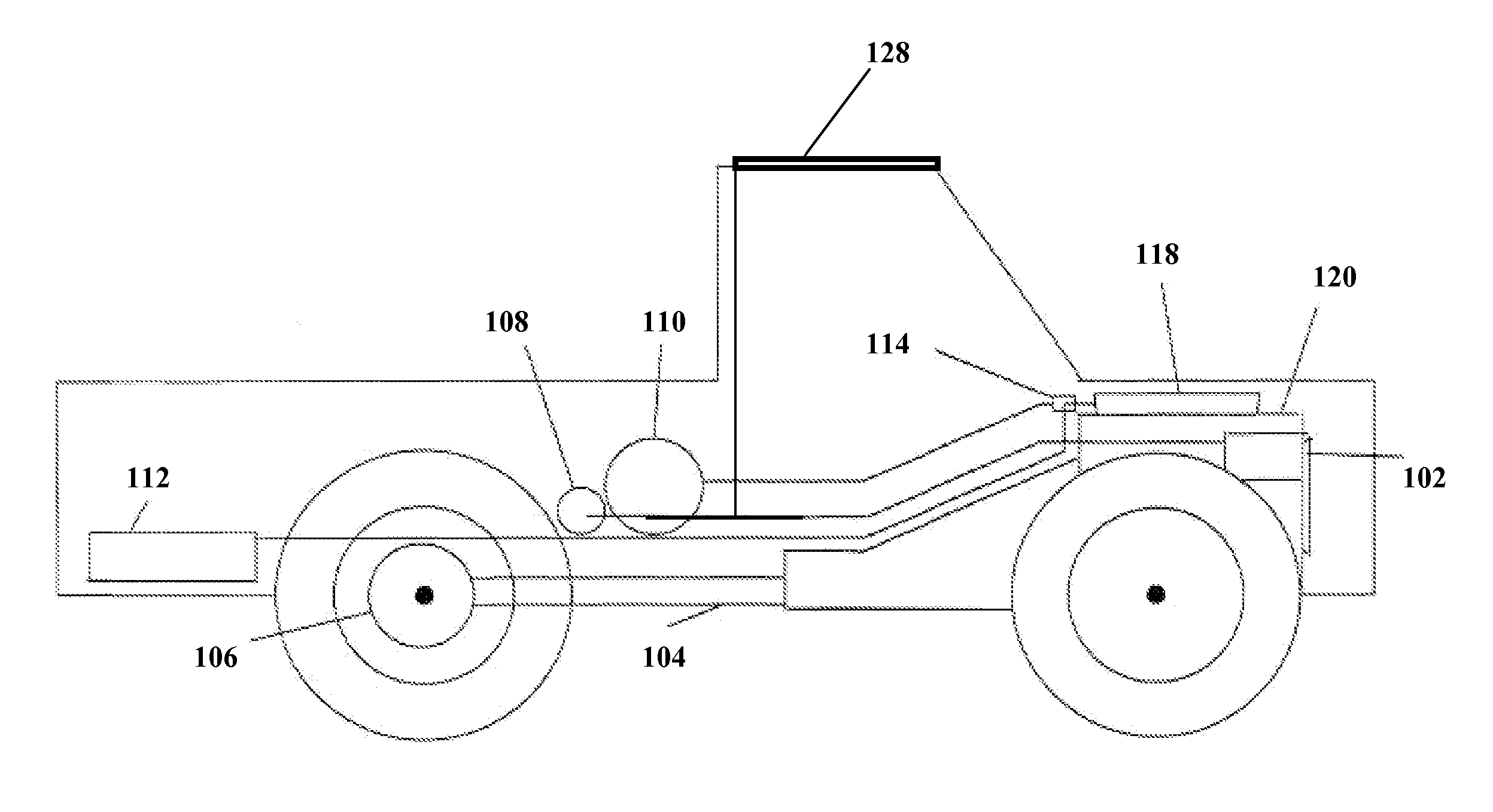
[0063] Turning to FIG. 1, an embodiment of the H-Brake is shown in which a generator / alternator of the H-Brake engages a vehicle's drive shaft. Generator / alternator 102 engages drive shaft 104 such that when the vehicle's brake is applied, a control member, for example a mechanical or electrical potentiometer or a computer control member, determines the proper means for slowing / stopping the vehicle which includes the use of the H-Brake, the conventional braking system, or a combination thereof. Drive axle 106 also engages drive shaft 104 for turning the wheels.

[0064] When the H-Brake is employed, generator / alternator 102 is started and kinetic / inertial energy from drive shaft 104 is transferred to generator / alternator 102 which generates electricity and slows the vehicle. The electricity so produced is fed to an electrolyzer 108 which converts water into gaseou...

example 3

H-Brake Kinetic / Inertial Energy Conversion, Storage and Fuel Mixture Control Kit: Generator / Alternator Friction-Coupled to Engine

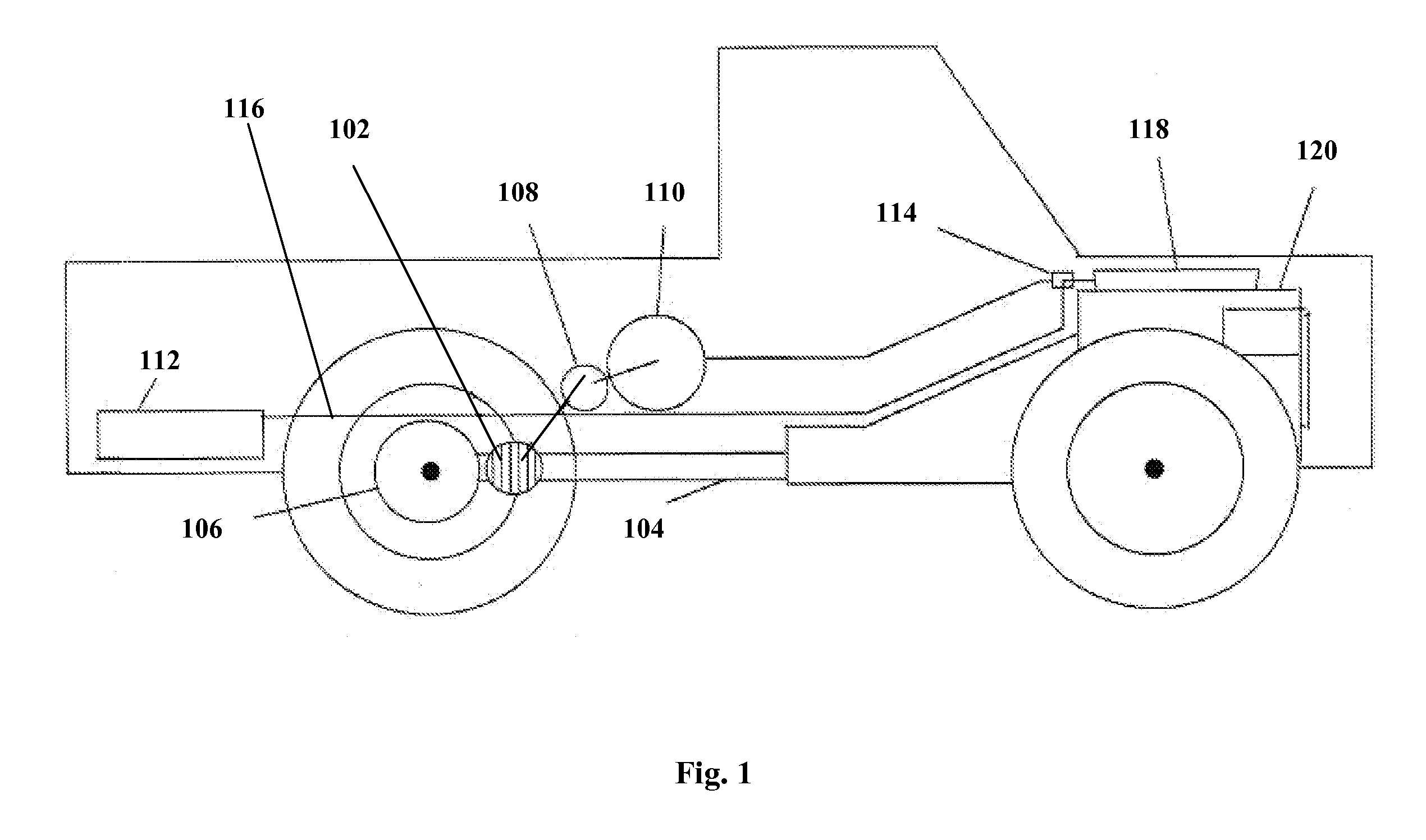
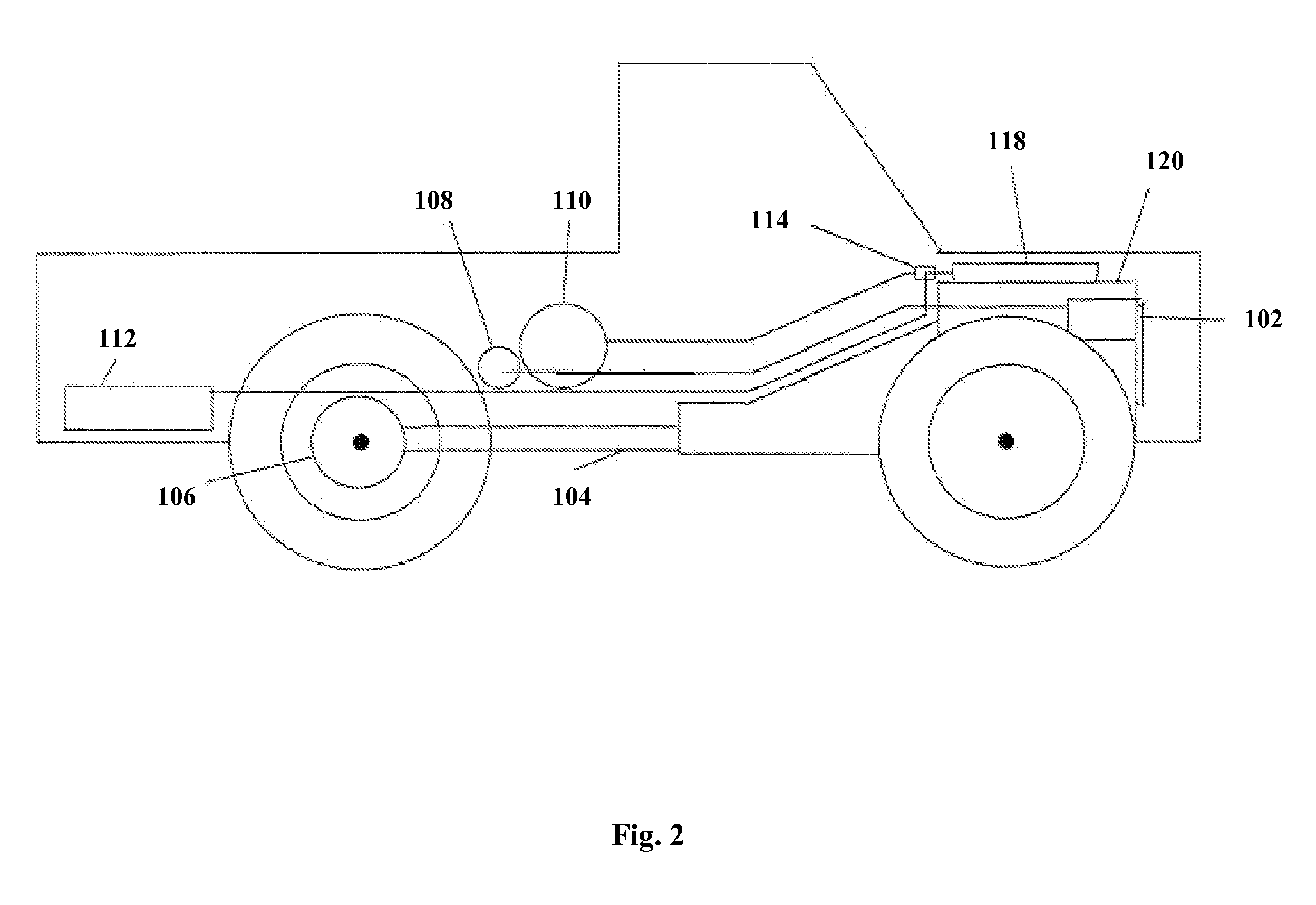
[0066] As shown in FIGS. 2 and 3, another embodiment of the H-Brake includes a generator / alternator friction-coupled to the vehicle's internal combustion engine. Turning to FIG. 2, generator / alternator 102 is friction-coupled (such as by a belt) to the internal combustion engine 120 such that when the vehicle's brake is applied, a control member determines the proper means for slowing / stopping the vehicle which includes the use of the H-Brake, the conventional braking system, or a combination thereof.

[0067] When the H-Brake is employed, generator / alternator 102 is started and kinetic / inertial energy from engine 120 is transferred to generator / alternator 102, slowing the engine and vehicle, and generating electricity. The electricity so produced is fed to electrolyzer 108 which converts water into gaseous hydrogen and oxygen. As shown in FIG. 2, a tank 11...


PUM


Abstract

The present invention relates to a system capable of using kinetic/inertial and renewable energy to generate hydrogen for use as a fuel in vehicles and other applications. In certain embodiments, this invention relates to a system in which hydrogen is generated during vehicle braking and which is operable with an internal combustion engine, and which can be retrofitted to vehicles with such an engine as well as to stationary combustion devices. Methods for generating hydrogen to power vehicles and vehicles utilizing the inventive technology are also provided. The present invention also relates to stationary devices, such as space heaters and water heaters, capable of generating hydrogen for use as a fuel additive therewith, and methods of generating hydrogen using such devices.

Description

RELATED APPLICATIONS [0001] This application is a continuation-in-part of and claims priority to U.S. patent application Ser. No. 11 / 383,536, filed on May 16, 2006; and further claims priority to U.S. Provisional Patent Application No. 60 / 681,023, filed on May 16, 2005; the subject matter of each of the aforementioned patent applications to which priority is claimed being hereby incorporated by reference in its entirety.FIELD OF THE INVENTION [0002] The present invention relates to systems capable of using kinetic / inertial and renewable energy to generate hydrogen as a fuel for use in vehicles and other applications. In certain other embodiments, this invention relates to a system for the generation and use of hydrogen fuel to be mixed with an existing fuel supply for use with a variety of mobile and stationary devices. In certain preferred embodiments, this invention relates to a system in which hydrogen is generated during a vehicle braking operation for use as a fuel with an inte...

Claims


Application Information

Patent Timeline
IPC IPC(8): F02B43/08F02B43/00F02B13/00
CPCB60K6/26B60K6/48B60K15/03006B60L8/003B60L8/00Y02T10/6221Y02T10/7083B60L7/10Y02T10/62Y02T10/7072
Inventor RUTLEDGE, KEITH
Owner RUTLEDGE KEITH
Why Eureka
Try Eureka