Submarine Boat

a technology for submersible boats and submarines, which is applied in the field of deepwater submersible research boats, submersible vessels, submarines, etc., can solve the problems of increasing the size of the submarine boat, the difficulty of handling, and the difficulty of hydrogen supply, so as to reduce the time required for start and energy amount to raise the temperature of the reformer, the effect of reducing the size of the hydrogen generating devi

Inactive Publication Date: 2007-09-13
GS YUASA INT LTD
View PDF5 Cites 5 Cited by
  • Summary
  • Abstract
  • Description
  • Claims
  • Application Information

AI Technical Summary

Benefits of technology

[0059] Since the submarine boat of the present invention has the hydrogen generating device loaded which can reform the fuel at 100° C. or less from a room temperature, which is extremely lower than the conventional reforming temperature, both time required for start and energy amount to raise the temperature of a reformer can be reduced, which realizes size reduction of a battery for start. Also, such effects are exerted that an insulating material for insulating a heat generated by the reforming device can be made unnecessary, and a hydrogen-containing gas generated from the hydrogen generating device can be easily supplied to the fuel cell without being cooled.
[0060] Moreover, since the hydrogen-containing gas generated from the hydrogen generating device does not contain CO, a CO removing device is not needed.
[0061] The hydrogen generating device used in the submarine boat of the present invention can generate hydrogen without supplying the electric energy from the outside to the hydrogen

Problems solved by technology

Hydrogen is generally used for a fuel of the fuel cell, but how to supply the hydrogen is a big problem in development of a submarine ship using a fuel cell.
But if the weight of a submarine boat is large, a buoyancy material corresponding to that is necessary, and the size of the submarine boat is inevitably increased to equip the buoyancy material, which is a problem.
Also, since the hydrogen is stored in a high-pressure gas state, attention should be paid to safety, and handling is difficult, which is another problem.
Though the metal hydride used in this hydrogen generating device is better in handling performance than high-pressure hydrogen gas, its reactivity is large unlike those using a fuel containing an organic compound as a hydrogen material, and some means is needed to prevent contact with water or alcohol, wh

Method used


Image

  • Submarine Boat
  • Submarine Boat
  • Submarine Boat

Examples


example 1

[0256] Illustrative examples of generating hydrogen based on the hydrogen generating device loaded on the submarine boat (open-circuit condition) as defined by Claim 2 will be presented below.

HYDROGEN GENERATING EXAMPLE 1-1

[0257] Hydrogen generating cells described in Example 1 (generating examples 1-1 to 1-10) have the same structure as that of representative DMFCs.

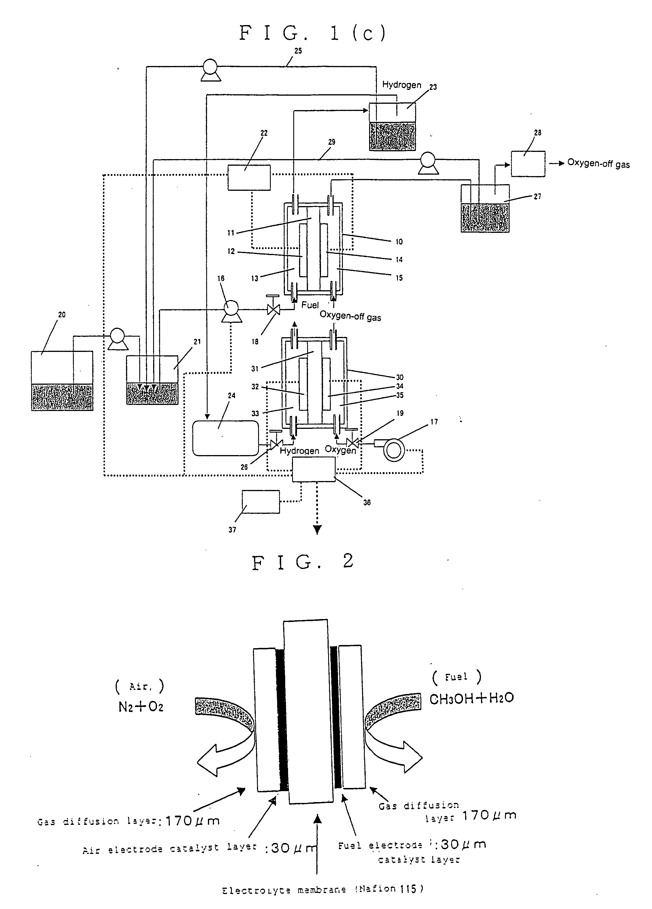
[0258] The structure of the hydrogen generating cell is outlined in FIG. 2.

[0259] The electrolyte membrane consists of a proton conducting electrolyte membrane provided by Dupont (Nafion 115); and the air electrode is obtained by immersing carbon paper (Toray) in a solution where polytetrafluoroethylene is dispersed at 5%, and baking the paper at 360° c. to make it water-repellent, and coating, on one surface of the paper, air electrode catalyst paste comprised of air electrode catalyst (carbon-supported platinum, Tanaka Precious Metal), fine powder of PTFE, and 5% Nafion solution (Aldrich). Thus, the air electrode e...

example 2

[0313] Illustrative examples of the hydrogen generating device loaded on the submarine boat as defined by Claim 3 of the invention (discharging condition) will be presented below.

HYDROGEN GENERATING EXAMPLE 2-1

[0314] The structure of hydrogen generating cells described in Example 2 (illustrative examples 2-1 to 2-8) with means for withdrawing electric energy is outlined in FIG. 21.

[0315] The hydrogen generating cells of Example 2 are the same in structure as those of hydrogen generating example 1-1 except that the cell comprises a fuel electrode as a negative electrode and an air electrode as a positive electrode with means for withdrawing electric energy.

[0316] The hydrogen generating cell was placed in an electric furnace where hot air was circulated. The cell was operated while the temperature (operation temperature) being kept at 50° C. with the flow rate of air to the air electrode kept at 10 to 100 ml / min and the flow of 1M aqueous solution of methanol (fuel) to the fuel e...

example 3

[0366] Illustrative examples of the hydrogen generating device loaded on the submarine boat as defined by Claim 4 of the invention (charging condition) will be presented below.

HYDROGEN GENERATING EXAMPLE 3-1

[0367] The structure of hydrogen generating cells described in Example 3 (hydrogen generating examples 3-1 to 3-8) with means for providing electric energy from outside is outlined in FIG. 42.

[0368] The hydrogen generating cells are the same in structure as those of hydrogen generating example 1-1 except that the cell comprises a fuel electrode as cathode and an oxidizing electrode as anode with means for providing electric energy from outside.

[0369] The hydrogen generating cell was placed in an electric furnace where hot air was circulated. The cell was operated while the temperature (operation temperature) being kept at 50° C. with the flow of air to the air electrode kept at 10 to 80 ml / min and the flow of 1M aqueous solution of methanol (fuel) to the fuel electrode kept a...


PUM


Abstract

A submarine boat is provided on which a hydrogen generating device which can supply hydrogen easily to a hydrogen storing means and can generate a hydrogen-containing gas at a low temperature is loaded.
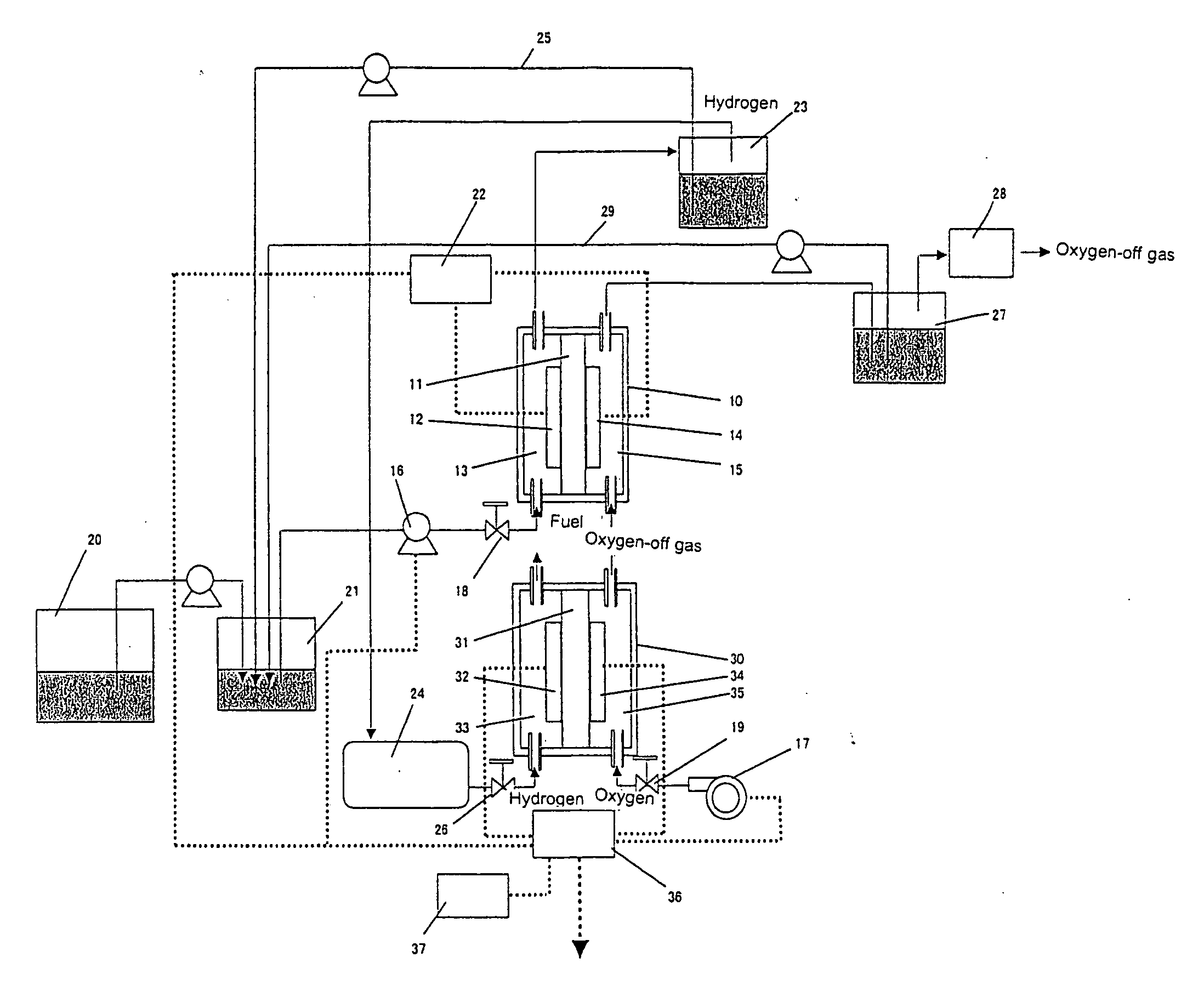
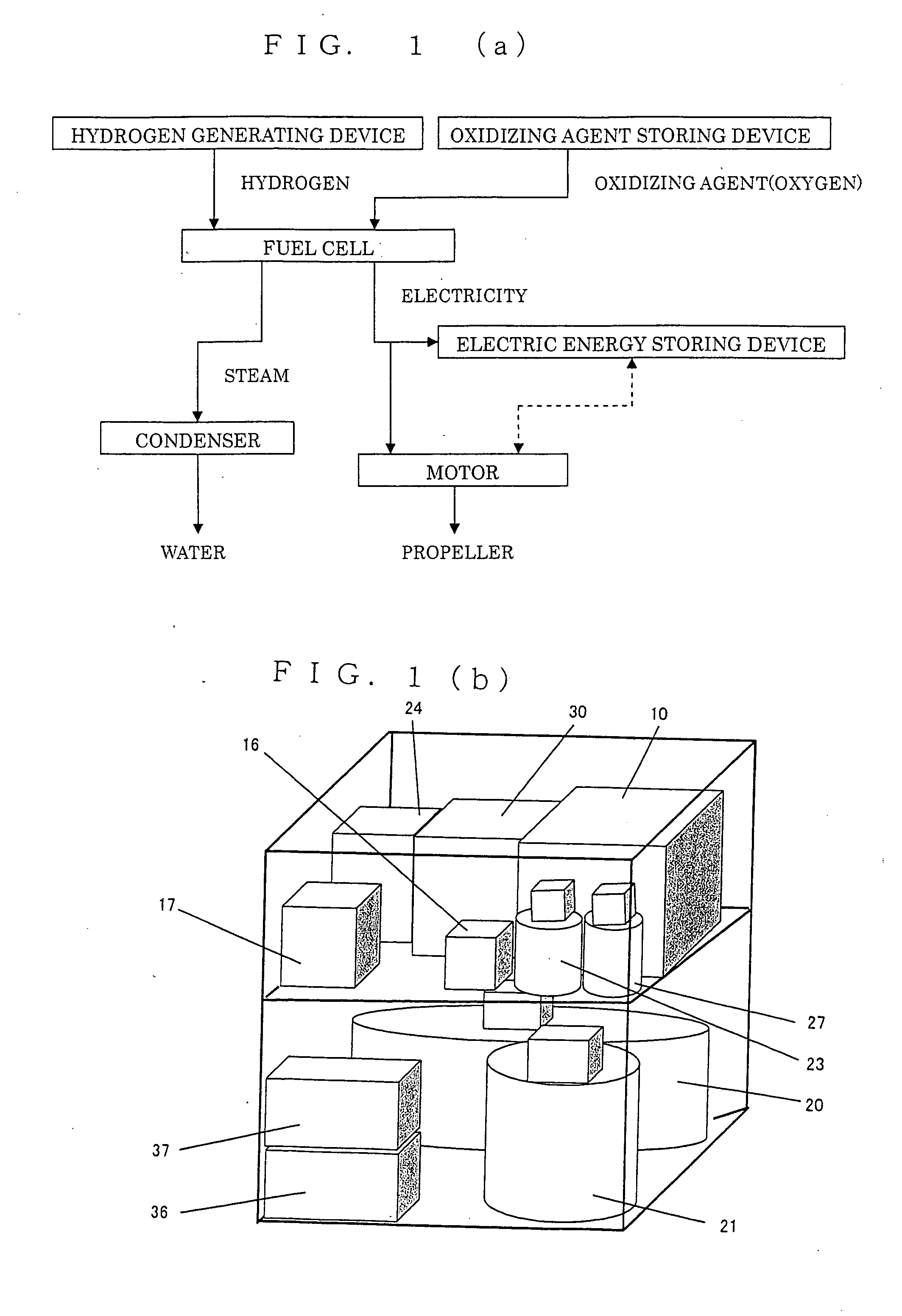
A submarine boat provided with a fuel cell (30) for power generation by supply of hydrogen and oxidizing agent, a hydrogen generating device (10) for generating a gas containing hydrogen to be supplied to the fuel cell, and propelling device driven by electricity generated by the fuel cell, characterized in that the hydrogen generating device is to generate a gas containing hydrogen by decomposing a fuel containing an organic compound, comprising a partition membrane (11), a fuel electrode (12) provided on one surface of the partition membrane, means (16) for supplying a fuel containing the organic compound and water to the fuel electrode, an oxidizing electrode (14) provided on the other surface of the partition membrane, means (17) for supplying an oxidizing agent to the oxidizing electrode, and means for generating and collecting the gas containing hydrogen from the fuel electrode. There are cases: (1) the hydrogen generating device is an open circuit having neither means for withdrawing electric energy to outside from a hydrogen generating cell constituting the hydrogen generating device, nor means for providing electric energy from outside to the hydrogen generating cell; (2) the hydrogen generating device has means for withdrawing electric energy to outside with the fuel electrode serving as a negative electrode and the oxidizing electrode as a positive electrode; and (3) the hydrogen generating device has means for providing electric energy from outside with the fuel electrode serving as cathode and the oxidizing electrode as anode.

Description

TECHNICAL FIELD [0001] The present invention relates to a deep-water submersible research boat, submersible vessel, submarine and the like on which a hydrogen generating device for supplying hydrogen to a fuel cell is loaded. [0002] Currently, as a power source for a deep-water submersible research boat, submersible vessel, submarine and the like, a fuel cell with excellent silence and efficiency are under development. Hydrogen is generally used for a fuel of the fuel cell, but how to supply the hydrogen is a big problem in development of a submarine ship using a fuel cell. [0003] In a conventional submarine boat, such a method is generally used that hydrogen is stored as a high-pressure hydrogen gas and this hydrogen is supplied to the fuel cell (See Patent Documents 1 to 3, for example). With this method, however, a gas container should be in a pressure-resistant structure and the mass of the container is increased. But if the weight of a submarine boat is large, a buoyancy materi...

Claims


Application Information

Patent Timeline
IPC IPC(8): H01M8/06H01M8/04B63G8/08C01B3/22C25B1/02
CPCB63G8/08B63H2021/003C01B3/22Y02E60/324C01B2203/066C25B1/02Y02T90/38C01B2203/0266Y02T90/40B63C11/00C01B3/00Y02E60/32
Inventor OKUYAMA, RYOICHIYAMAMOTO, YOSHIHIROMOTOI, MASASHIASHIDA, KATSUJI
Owner GS YUASA INT LTD
Why Eureka
Try Eureka