This helps you quickly interpret patents by identifying the three key elements:
Problems solved by technology
Method used
Benefits of technology
[0015]The present invention has been achieved to solve the above-mentioned problems, and has an object to obtain a differential absorption lidar apparatus capable of measuring the co
Problems solved by technology
First, in the coherent lidar, coherency at an optical carrier level of laser light to be transmitted/received is important, and it is also important to transmit/receive laser light having a very small line width. Furthermore, in order to perform a long-distance measurement of the order of 100 km as in the observation of the vicinity of the ground from the artificial satellite, a high transmission power of laser light is required. It is very difficult to allow laser light with such a small line width and a high power to be operated under strict constraints required when the coherent lidar is mounted on the satellite, which makes it difficult to maintain the reliability of the apparatus.
However, it is difficult to successively grasp the Doppler frequency shift caused by the above-mentioned moving speed.
Therefore, it
Method used
Image
Click on the blue label to locate the original text in one second.
Reading with bidirectional positioning of images and text.
Examples
embodiment 1
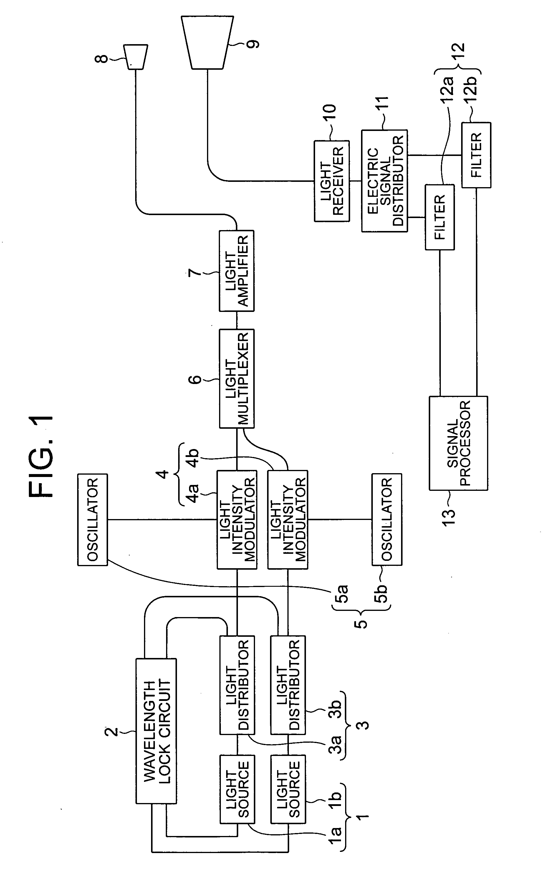
[0022]A differential absorption lidar apparatus according to Embodiment 1 of the present invention will be described with reference to FIG. 1. FIG. 1 is a block diagram showing a configuration of the differential absorption lidar apparatus according to Embodiment 1 of the present invention. Hereinafter, in each figure, like reference numerals denote like corresponding components.
[0023]In FIG. 1, the differential absorption lidar apparatus according to Embodiment 1 includes a light source 1 (1a and 1b), a wavelength lock circuit 2, a light distributor 3 (3a and 3b), a light intensity modulator 4 (4a and 4b), an oscillator 5 (5a and 5b), a light multiplexer 6, a light amplifier 7, a transmission optical system 8, a reception optical system 9, a light receiver 10, an electric signal distributor 11, a filter 12 (12a and 12b), and a signal processor 13.
[0024]The light source 1 (1a and 1b), the light distributor 3 (3a and 3b), and the wavelength lock circuit 2 constitute light signal gene...
embodiment 2
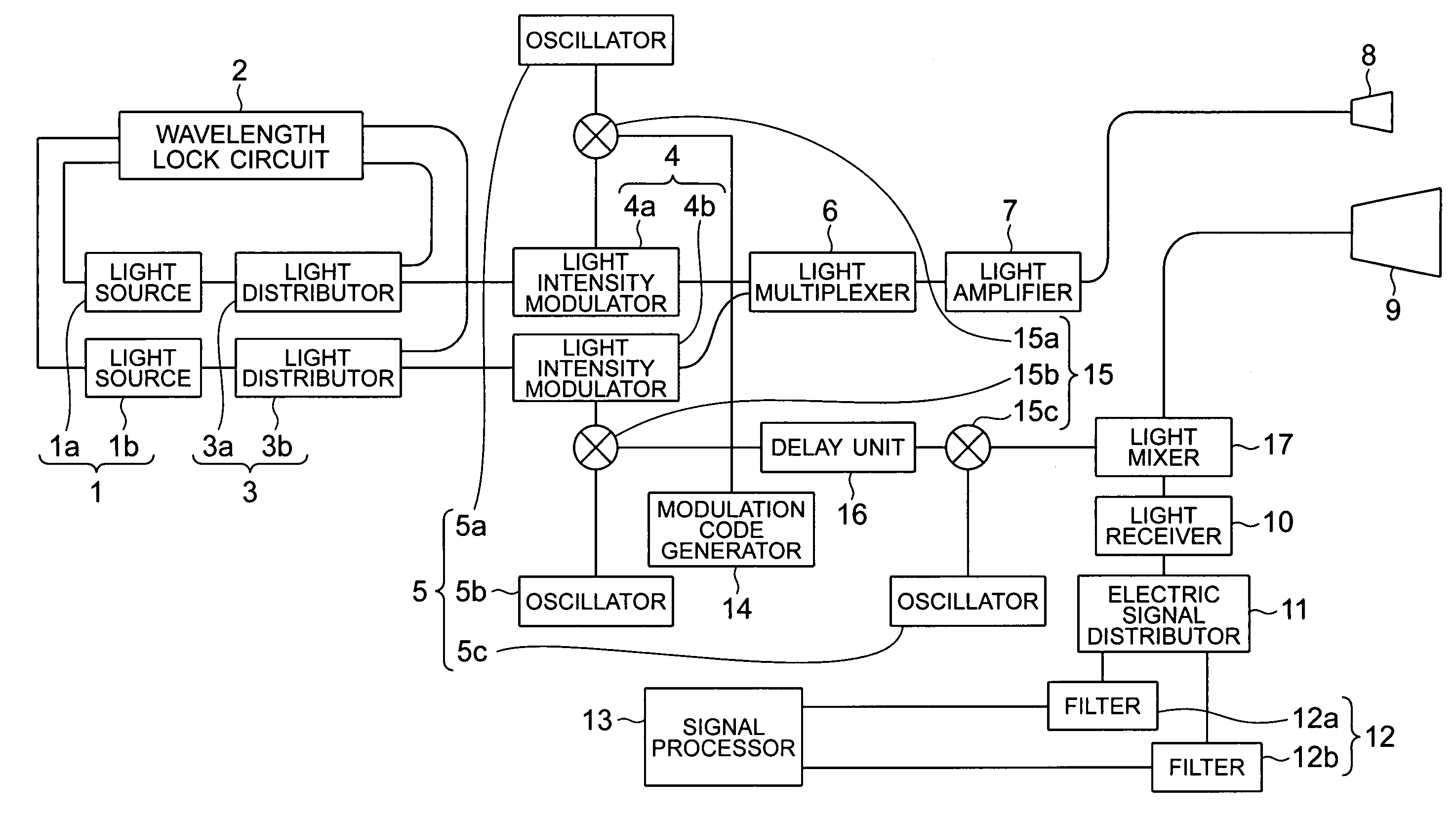
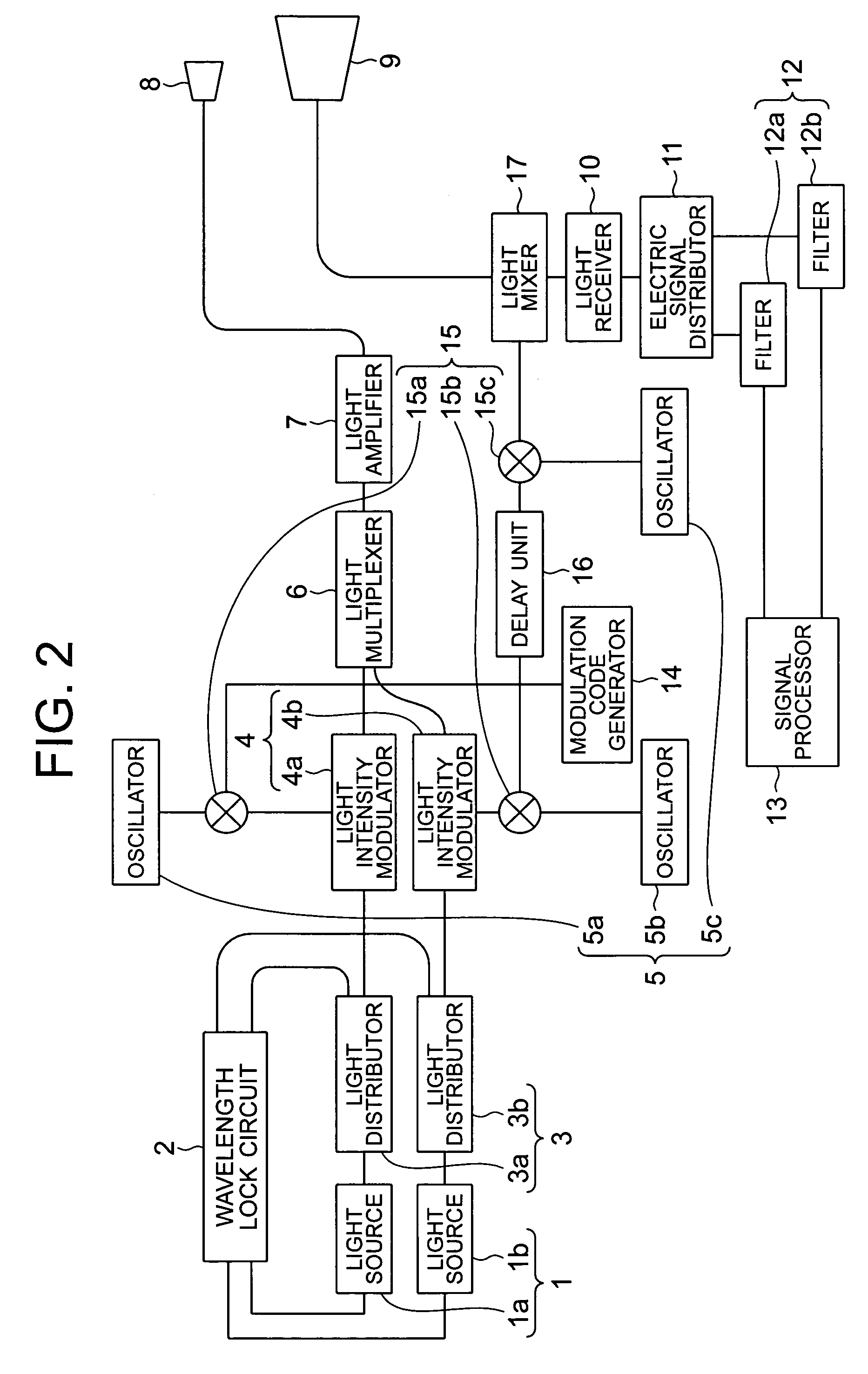
[0056]A differential absorption lidar apparatus according to Embodiment 2 of the present invention will be described with reference to FIGS. 2 and 3. FIG. 2 is a block diagram showing a configuration of the differential absorption lidar apparatus according to Embodiment 2 of the present invention.
[0057]In FIG. 2, the differential absorption lidar apparatus according to Embodiment 2 includes a modulation code generator 14, an electric mixer 15 (15a, 15b, and 15c), a delay unit 16, and a light mixer 17, in addition to the above-mentioned components of the differential absorption lidar apparatus in Embodiment 1.
[0058]Furthermore, although there are two oscillators 5 in Embodiment 1, there are three oscillators 5 (5a, 5b, and 5c) in Embodiment 2. The other components are the same as those shown in Embodiment 1.
[0059]The light source 1 (1a and 1b), the light distributor 3 (3a and 3b), and the wavelength lock circuit 2 constitute the light signal generation means. Furthermore, the oscilla...
PUM
Abstract
A differential absorption lidar includes: a light signal generation unit for generating first, second CW light signals with first, second wavelengths having different absorption coefficients with respect to a target, a light intensity modulation unit for subjecting the first, second CW light signal to intensity modulation with a first, second CW modulation signal having a first, second frequency in a baseband, a radiation unit for multiplexing the first, second CW light signals with the intensity modulated, forming the multiplexed light signals with two wavelengths in a predetermined beam size, and radiating the light signals, a reception unit for directly detecting scattered light from the target and converting the scattered light into an electrical signal, and a signal processing unit for extracting only the first, second frequency components from the electric signal, and detecting the concentration of the target from a difference in an amplitude of time wavelengths between two signals.
Description
BACKGROUND OF THE INVENTION[0001]1. Field of the Invention[0002]The present invention relates to a differential absorption lidar apparatus for transmitting laser light with at least two wavelengths in the air and receiving scattered light from a target (gas to be measured, such as carbon dioxide, ozone, or water vapor), and measuring the concentration of the target in the air from a difference in intensity of received light regarding each wavelength.[0003]2. Related Background Art[0004]A conventional differential absorption lidar apparatus transmits laser light with two wavelengths having very high coherency in the air, receives scattered light from the ground or an aerosol to be a target, and heterodyne-detects the received light and local light. The differential absorption lidar apparatus obtains a frequency spectrum of a signal obtained by heterodyne-detection, and detects received light regarding each of the two wavelengths from the frequency spectrum (see, for example, “Coheren...
Claims
Application Information
Patent Timeline
Application Date:The date an application was filed.
Publication Date:The date a patent or application was officially published.
First Publication Date:The earliest publication date of a patent with the same application number.
Issue Date:Publication date of the patent grant document.
PCT Entry Date:The Entry date of PCT National Phase.
Estimated Expiry Date:The statutory expiry date of a patent right according to the Patent Law, and it is the longest term of protection that the patent right can achieve without the termination of the patent right due to other reasons(Term extension factor has been taken into account ).
Invalid Date:Actual expiry date is based on effective date or publication date of legal transaction data of invalid patent.