Method for improving gasification efficiency through the use of waste heat

Inactive Publication Date: 2007-09-27
ZEROPOINT CLEAN TECH
View PDF4 Cites 82 Cited by
  • Summary
  • Abstract
  • Description
  • Claims
  • Application Information

AI Technical Summary

Benefits of technology

[0014] The present invention comprises, in one exemplary embodiment, a method which allows the waste heat generated from an external process, which is fueled by syngas, to be recycled into a gasification process to enhance the energy density of the syngas produced as well as the overall gasification efficiency of the system. The invention also relates to a method of utilizing the waste heat contained in a stream exiting in the syngas-fueled process to vaporize water and produce steam. The steam is then upgraded by first exchanging energy with the hot syngas exiting the gasifier and then within the gasifier itself to a temperature where significant steam gasification of the biomass occurs. The process within the gasifier is driven by introducing a small amount of air into the gasifier such that some biomass is directly combusted to provide the heat required by the endothermic proce

Problems solved by technology

In reality this is not easily achieved, although with good thermal management it is possible to operate with energy efficiencies in excess of 90%.
One disadvantage of gasification is that the gas stream produced has a relatively weak energy density.
This low energy density detracts from the economics of compressing the gas and transporting through pipelines to anywhere other than over short to moderate distances.
On a wet basis this value can be substantially less and can even be less than zero, indicating that the fuel is not capable of burning in a sustainable manner while liberating

Method used


Image

  • Method for improving gasification efficiency through the use of waste heat
  • Method for improving gasification efficiency through the use of waste heat
  • Method for improving gasification efficiency through the use of waste heat

Examples


Example

Example 1

[0021] A 15 cm, down-draft stratified gasifier with an integral tar cracking and hydrocarbon reforming lower chamber was used to convert biomass into syngas. In the upper zone the biomass undergoes the decomposition process commencing with devolatization followed by flaming pyrolysis and finally char gasification. In the lower zone a small amount of air is introduced into the syngas such that a small fraction is further oxidized. The heat liberated by this oxidation allows higher order hydrocarbons and tars to be broken down into carbon monoxide and hydrogen. The result of the thermal treatment is that a syngas which is essentially free of tars and higher order hydrocarbons is produced. The air flow to the gasifier was adjusted such that the maximum bed temperature was 850° C. The syngas produced exiting the system was cooled to 40° C. such that any condensable matter is liquefied. The syngas was filtered using a 5 micron polyester filter, passed through a blower and was t...

Example

Example 2

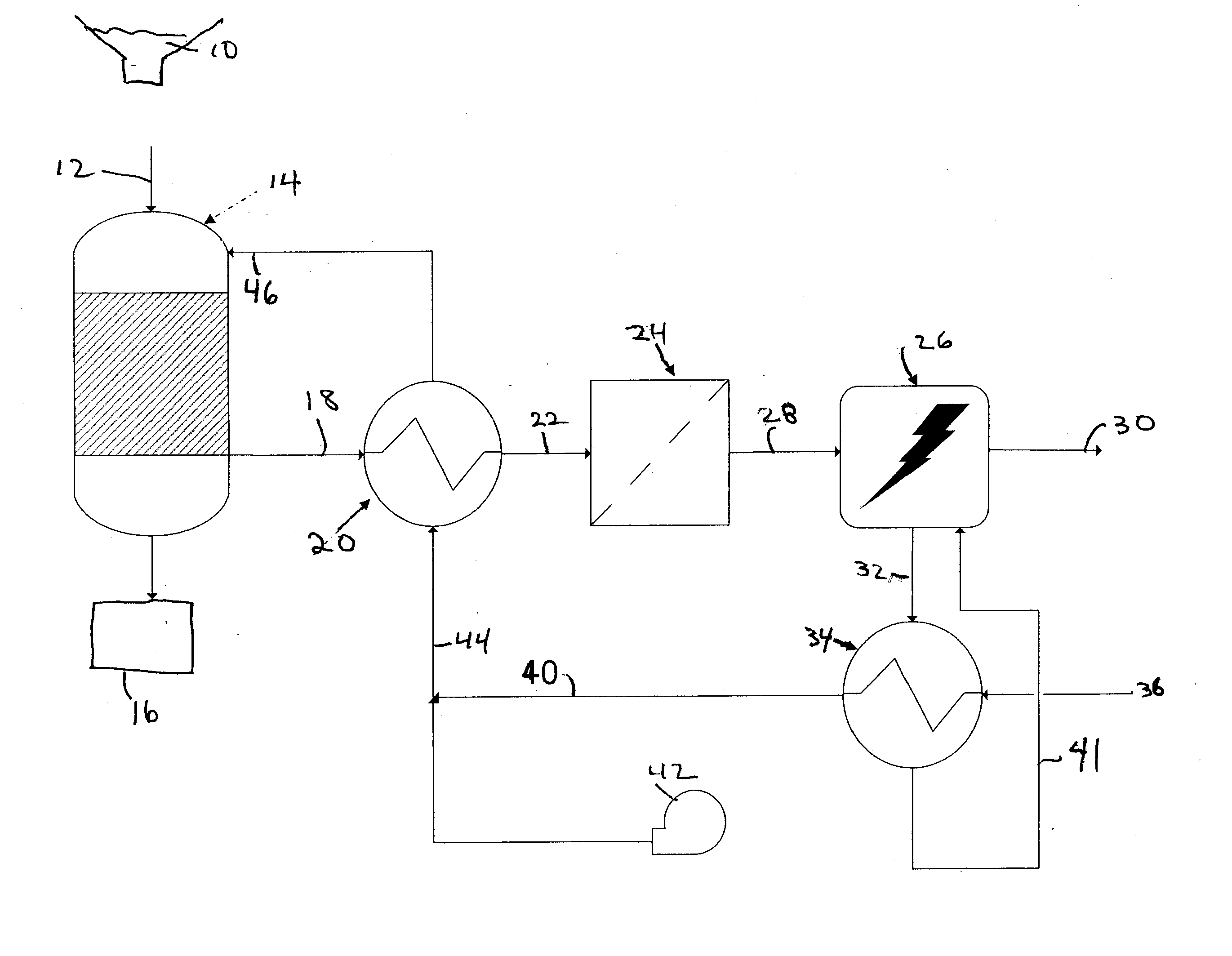
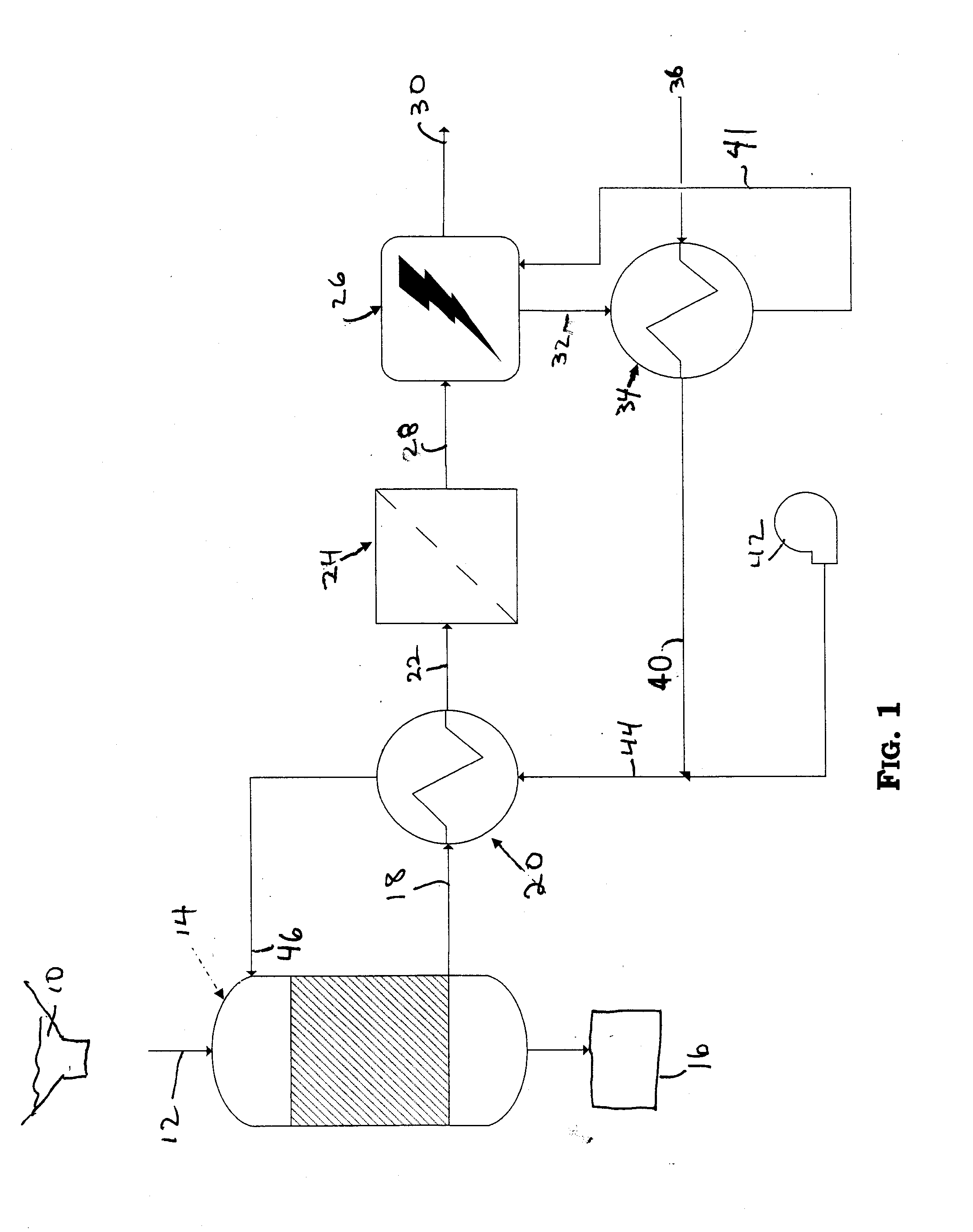
[0024]FIG. 1 illustrates an exemplary, nonlimiting embodiment of a continuous process for recycling waste heat from an electricity generator powered by an internal combustion engine into a gasification system. The result is to both enrich the quality of the gas being produced there and improve the overall thermal efficiency of the gasifier. Biomass 10 is fed via stream 12 into a gasification 14. In the gasifier 14, volatile matter and a good fraction of the fixed carbon is converted into gaseous components. The ash, non-volatiles and any unconverted fixed carbon exit via the ash outlet into a collector 16. The hot syngas stream 18 exits the gasifier 14 and is partially cooled in a booster heat exchanger 20. A number of heat exchangers are suitable for this operation, including, but not limited to, shell and tube, plate duct, welded plate and diffusion bonded plate heat exchangers. It may be advantageous to orientate the exchanger 20 such that the gas stream flows in a vert...


PUM


Abstract

A method for recycling the waste heat generated from an external process, which is fuelled by syngas, into a gasification process to enhance the energy density of the syngas produced as well as the overall gasification efficiency of the system. A method is provided for utilizing the waste heat contained in a stream exiting in the syngas fueled process to vaporize water and produce steam. The steam is then upgraded by first exchanging energy with the hot syngas exiting the gasifier and then within the gasifier itself to a temperature where significant steam gasification of the biomass occurs. The process within the gasifier is driven by introducing a small amount of air into the gasifier such that some biomass is directly combusted to provide the heat required by the process.

Description

CROSS-REFERENCE TO RELATED APPLICATIONS [0001] This application claims benefit of co-pending U.S. Provisional Patent Application Nos. 60 / 785,519, filed Mar. 24, 2006, entitled METHOD TO IMPROVE GASIFICATION EFFICIENCY THROUGH THE USE OF WASTE HEAT, and 60 / 785,520, filed Mar. 24, 2006, entitled GASIFICATION SYSTEMS, and commonly assigned to the assignee of the present application, the disclosures of which are incorporated by reference in their entirety herein. FIELD OF THE INVENTION [0002] The present invention relates to gasifier equipment and to the process of gasification of carbon containing solids into combustible gases. The improvement may be used to enrich the calorific density and hydrogen content of the produced syngas while simultaneously improving the thermal efficiency of the gasification process. BACKGROUND OF THE ART [0003] Gasification processes convert carbon-containing solids of liquids into combustible gases that ideally contain all the energy originally present in ...

Claims


Application Information

Patent Timeline
IPC IPC(8): C10L3/00
CPCC10J3/00C10J2300/0916C10J2300/0956C10J2300/0973Y02E20/18C10J2300/1838C10J2300/1861C10J2300/1884C10J2300/1892C10J2300/1671Y02P20/129Y02P20/145
Inventor LEVESON, PHILIP D.GAUS, JOHN PAUL
Owner ZEROPOINT CLEAN TECH
Why Eureka
Try Eureka